
User's Manual
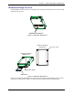
Table Of Contents
- Introduction
- General Characteristics
- Feature Details
- Feature Descriptions
- Applications
- Mechanical Design Overview
- Mechanical Dimensions
- Climatic and Mechanical Environment Testing Compliance
- Introduction
- 50-Pin Connector Interfaces
- Flashing LED
- SIM Interface
- RF Interface
- DTE/DCE Interface Rates
- Serial Test/Demo Board Components
- Serial Test/Demo Board Block Diagram
- General Guidelines for the Use of the ModemModule
- Reference Documents
- Related Manuals
- Additional Information
- Safety Precautions
- Regulatory Standards Compliance
- Where to Find SMD Connectors
- GSM Antenna
- SIM Card Holder
- LIST OF TABLES

Chapter 1 – Product Description & Specification
Wireless ModemModule MTMMC-G-F1 and MTMMC-G-F2 Developer’s Guide 7
GSM Circuit Data Features
· Data circuit asynchronous, transparent and non transparent up to 14,400
· bits/s
· Automatic fax group 3 (Class 1 & 2)
· Alternate speech and fax
· MNP2, V.42bis data compression
GPRS Packet Data Features
· GPRS Class 10
· Coding Schemes: C1S1 to CS4
GSM Supplementary Services
· Call Forwarding
· Call Barring
· Multiparty
· Call Waiting and Call Hold
· Calling Line Identity
· Advice of Charge
· USSD
· Closed User Group
· Explicit Call Transfer
Other Features
· ME+SIM phone book management
· Fixed Dialing Number
· SIM Toolkit Class 2
· SIM, network and service provider locks
· Real Time Clock
· Alarm management
· Software upgrade through Xmodem protocol
· UCS2 character set management
Interfaces
Single antenna interface
Internal SIM interface: 3V only
External SIM interface: 3V or 5V
For Data Operation:
Serial link
Remote control by AT commands (GSM 07.07 and 07.05)
Baud rate from 300 to 115,200 bits/s
From 300 up to 38400 bits/s with autobauding
The integrated modem has a sole 50-pin connector, which gathers all the interface signals in order to facilitate its
integration. It has an integrated SIM card holder as well as a standard RF connector type MMCX. The concept
of the integrated modem has been defined to integrate on a sole device:
· a single connector has been used that is standard and easy to find (it is supplied worldwide);
this connector includes all of the modem’s analog and digital connections
· One standard easy to find RF connector. See RF connector section in Chapter 3: Electrical
Characteristics;
· One SIM card holder. See SIM section in Chapter 3: Electrical Characteristics.