
User's Manual


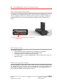
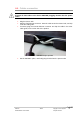


Table Of Contents

IMP400 11/15 Copyright © 2014 Ingenico
900021685 R11 000 01/0615 All rights reserved
4.5. Fixing the cradle on its support
The IMP400 is equipped with keyholes fixations on the bottom in order to fix it to its
support, if need be.
Location of the keyhole fixations
The center distance between the two fixations is 340mm.
Mounting instructions:
Place 2 screws or other fixing devices 340mm from each other, on the intended
support of the IMP400.
Align the widest part of each keyhole with the corresponding screw, and lower
on the support.
Slide it in place by gently pulling towards you until each screw reaches the end
of the keyhole.
4.6. iSMP3 Docking
Before docking the iSMP3, verify that the IMP400 is up and running. The main
LED should be lit green to indicate so.
Hold the iSMP3 over one of the docking slots, and lower gently into the slot,
without dropping it.
The guide located in the slot is intended to slide into the Swipe Card Reader.
Once docked, the LEDs on the slot will light up. The charging LED will be Red
or Green depending on the charge level of the device. The blue LED will blink
while communication with the device is initialized.
Once the blue LED is lit solid, the iSMP3 is successfully docked and can be left
to charge and synchronize.
Keyhole fixations on the IMP400 casing (bottom
view)