
User's Guide

iWL2xx Wireless Series • 19/32
Copyright © 2011 Ingenico
900003061 R11 000 05/1122
All rights reserved
5.1.2.
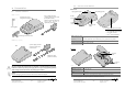
Base downside connections
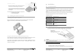
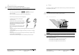
• Remove base trapdoor pushing on clips
( see clips location at red arrows)
• Connect all downside connections
• Use “path for wires” to
manage cable exit
• Close trapdoor
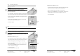
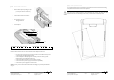
G= Serial link COMØ – RS232 (optional) H= Serial link COM1 – RS232 (optional)
I = Modem socket (optional)
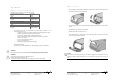
Follow the below instru ctions to connect the base to the telephone network :
• Disconnect power supply unit (socket B) in order to switch off the base prior to
connecting it to the appropriate network.
• Connect telephone cable equipped if necessary with us er country specific
telephon e plug, to the telephone network.
• Connect the other end of the wire to the base (socket I).
• Connect the mains power supply wire to the base (socket B).
• Connect base power supply block to the mains .
Socket I : TNV-3 circuit: Telecommunication Network Voltage, as per safety standard EN
60950-1.
Path for wires
G
H
I
B
iWL2xx Wireless Series • 20/32
Copyright © 2011 Ingenico
900003061 R11 000 05/1122
All rights reserved
5.1.3.
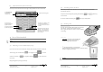
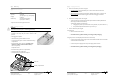
Fasten your base on desk
It is possible to fasten base on desk thanks to buttonholes located on base bottom casing.
Uses pattern beside to best locate screws position:
WARNING
Base must be set in horizontal position to insure terminal link work properly. This remains true when
buttonholes are used. Uses wall docking station accessory to fasten base in non horizontal position.