
Specifications


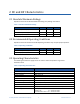
Table Of Contents
- Revision History
- 1 Overview
- 2 DC and RF Characteristics
- 3 Electrical Interface
- 4 Safety Considerations
- 5 Regulatory Considerations
- 6 Installation of TRN-2013 Board
- 7 Provisioning
- Appendix A RF Test Mode Interface
- A.1 Normal Operating Mode 0
- A.2 Non-Persistent Idle / Factory Test Mode 1
- A.3 Persistent Idle / Factory Test Mode 2
- A.4 Non-Persistent Node RF Test Mode 3
- A.5 Persistent Node RF Test Mode 4
- A.6 Non-Persistent Manufacturing Cal Mode 5
- A.7 Persistent Manufacturing Cal Mode 6
- A.8 Non-Persistent Meter Diagnostic Mode (Not Yet Implemented)
- A.9 Setting eMCM to Test Mode 1 - Non-Persistent Idle Factory Test Mode
- A.10 Setting eMCM to Test Mode 2 - Persistent Idle Factory Test Mode
- A.11 Setting eMCM to Test Mode 3 - Non-Persistent RF Test Mode
- A.12 Setting eMCM to Test Mode 4 - Persistent RF Test Mode
- Appendix B REACH Compliance Statements
- Appendix C Abbreviations and Terms
- Appendix D TRN-2013 Mechanical Drawing and Schematics

TRN-2013 Integration Specification DC and RF Characteristics
On-Ramp Wireless Confidential and Proprietary 10 014-0057-00 Rev. B
Parameter TRN-2013 Module
Maximum Allowable Path Loss 172 dB (FCC/IC)
Current Consumption 0.22A max. @ 4VDC (during TX
1
)
0.20A max. @ 4VDC (during RX
2
)
Operating Temperature -40°C to 85°C
Relative Humidity 5% to 95% non-condensing
Security AES 128-bit payload encryption, mutual authentication of network
elements
Certifications FCC and IC EMC certifications for TRN-2013 are pending.
Meter ANSI and Unintentional Radiator certifications required once
integrated into the meter product.
Note: Specifications subject to change
NOTE 1: During TX mode the supercap charger is disabled to reduce peak currents.
NOTE 2: During RX mode the supercap charger is enabled. The supercap charge current is
limited to about 110mA.
2.4 Power Supplies
The TRN-2013 utilizes two main power supplies when it is functioning:
1. Main switching power supply (3.3VDC output).
This main buck-boost power supply is operating at all times. It supplies power to all digital
and radio circuits.
2. Supercap Charger (~4.4VDC output).
This boost type switching power supply is used to charge the super capacitors. It can only
operate with an input supply up to about 4.4VDC. It is in use at all times when primary
power is applied. Once primary power is interrupted this power supply is disabled and the
super caps supply power to the main switching power supply.
Additionally the microNode module on the TRN-2013 printed circuit board has its own switching
power supply (buck-boost) that uses, as its source, the main switching power supply of the TRN-
2013.