
Specifications


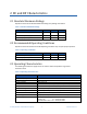
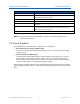
Table Of Contents
- Revision History
- 1 Overview
- 2 DC and RF Characteristics
- 3 Electrical Interface
- 4 Safety Considerations
- 5 Regulatory Considerations
- 6 Installation of TRN-2013 Board
- 7 Provisioning
- Appendix A RF Test Mode Interface
- A.1 Normal Operating Mode 0
- A.2 Non-Persistent Idle / Factory Test Mode 1
- A.3 Persistent Idle / Factory Test Mode 2
- A.4 Non-Persistent Node RF Test Mode 3
- A.5 Persistent Node RF Test Mode 4
- A.6 Non-Persistent Manufacturing Cal Mode 5
- A.7 Persistent Manufacturing Cal Mode 6
- A.8 Non-Persistent Meter Diagnostic Mode (Not Yet Implemented)
- A.9 Setting eMCM to Test Mode 1 - Non-Persistent Idle Factory Test Mode
- A.10 Setting eMCM to Test Mode 2 - Persistent Idle Factory Test Mode
- A.11 Setting eMCM to Test Mode 3 - Non-Persistent RF Test Mode
- A.12 Setting eMCM to Test Mode 4 - Persistent RF Test Mode
- Appendix B REACH Compliance Statements
- Appendix C Abbreviations and Terms
- Appendix D TRN-2013 Mechanical Drawing and Schematics

TRN-2013 Integration Specification Contents
On-Ramp Wireless Confidential and Proprietary iv 014-0057-00 Rev. B
A.3 Persistent Idle / Factory Test Mode 2 ...................................................................................... 21
A.4 Non-Persistent Node RF Test Mode 3 .................................................................................... 21
A.5 Persistent Node RF Test Mode 4 ............................................................................................ 22
A.6 Non-Persistent Manufacturing Cal Mode 5 ............................................................................. 22
A.7 Persistent Manufacturing Cal Mode 6 ..................................................................................... 22
A.8 Non-Persistent Meter Diagnostic Mode (Not Yet Implemented) ............................................. 23
A.9 Setting eMCM to Test Mode 1 - Non-Persistent Idle Factory Test Mode ................................ 23
A.10 Setting eMCM to Test Mode 2 - Persistent Idle Factory Test Mode ..................................... 24
A.11 Setting eMCM to Test Mode 3 - Non-Persistent RF Test Mode ............................................ 24
A.12 Setting eMCM to Test Mode 4 - Persistent RF Test Mode .................................................... 25
Appendix B REACH Compliance Statements ...................................................... 26
Appendix C Abbreviations and Terms ................................................................. 28
Appendix D TRN-2013 Mechanical Drawing and Schematics ............................ 30
Figures
Figure 1. On-Ramp Wireless Total Reach Network ......................................................................... 7
Figure 2. TRN-2013 Printed Circuit Board ..................................................................................... 11
Table 3. Pins and Signals for J500 Signal and Power Connector ................................................. 12
Figure 4. Meter Test Connection Diagram ..................................................................................... 13
Figure 5. TRN-2013 Block Diagram ............................................................................................... 14
Figure 6. TRN-2013 Product Label ................................................................................................ 17
Figure 7. Meter Assembly with a TRN-2013 MCM ........................................................................ 19
Figure 8. Mechanical Dimensions for TRN-2013 ........................................................................... 31
Figure 9. TRN-2013 board schematic, page 1 ............................................................................... 32
Figure 10. TRN-2013 schematic, page 2 ....................................................................................... 33
Figure 11. TRN-2013 schematic, page 3 ....................................................................................... 34
Figure 12. TRN-2013 schematic, page 4 ....................................................................................... 35
Figure 13. TRN-2013 schematic, page 5 ....................................................................................... 36
Tables
Table 1. Absolute Maximum Ratings ............................................................................................... 9
Table 2. Operating Conditions ......................................................................................................... 9
Table 3. Operating Characteristics .................................................................................................. 9
Table 4. ESD Rating ...................................................................................................................... 12