
User's Manual


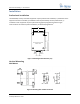

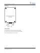
Table Of Contents

Ultra-Link Processing™ - Access Point
Access Point User’s Guide 012-0001-00 P a g e | 6
On-Ramp Wireless © 2010
Note: Mount the AP directly to non-metallic wall studs if possible; do not secure the AP to a drywall
surface. When stud spacing exceeds the AP’s mounting dimensions, secure ½” plywood to the
studs and secure the AP to the plywood mount.
1. Place the AP against the mounting location.
2. Drill a 3/16” hole through each of the mounting tabs and into the mounting surface.
3. Insert a ¼” x 1” wood screw thru each mounting tab and into the mounting surface.
4. Tighten each screw until it is secure against the mounting surface.
5. Ground the AP to an appropriate ground.
Pole Mount
1. Turn the AP upside down and orient it so that the antenna outputs face you (see Figure 3:
Mounting hole dimensions (cm)). The mounting hole dimensions will be visible.
2. Place the slotted struts over the mounting holes. Orient the struts horizontally.
3. Slide a flat washer onto the 5/16” hex head thread cutting screw.
4. Insert the screw and washer thru the slotted struts and into the AP housing’s mounting holes.
5. Using a 10mm nut driver, thread the screw into the mounting hole.
6. Tighten each screw until snug against the slotted strut.
Note: Avoid over-tightening the screws
7. When both slotted struts are secured to the AP enclosure, slide a 1 strut mount clamp (1” or 2”
depending on the application) onto each slotted strut.
8. Once the strut mount clamps mounted on the struts, slide the AP onto the pole. Make sure that
the antenna cables face downward.
9. Tighten the mounting clamp bolts so that the AP enclosure is secure against the pole.
Horizontal Mounting
Rack Mount
Orient the Access Point enclosure so that the antenna connectors and indicator lights are facing you.
1. Loosen the 4 top cover securing screws using a flat-blade 5/16” X 6” screwdriver.
Note The top cover screws are retained
2. Lift the cover strait up and open it by lifting the right hand side.
3. Remove the two keeper screws located next to the hinge posts.
4. Lift the cover off of the enclosure and set aside.
a. Insert the keeper screws into their mounting holes and partially screw them down to avoid
loss.
5. Using a ¼” x 4” flat blade screwdriver, loosen the mounting tabs.
6. Rotate the mounting tabs 90 degrees from their horizontal orientation to a vertical orientation.