
Owner's Manual


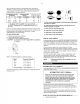


Position of weight and thrust pin when unit is operating.
TUBE CONNECTION
TO ATMOSPHERE
t
!
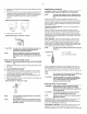
Position of weight and thrust pin when unit is stopped.
TUBE CONNECTION
TO ATMOSPHERE
STARTING UNLOADING SYSTEM (PRESSURE
LUBRICATED MODELS)
Pressure lubricated compressors use a hydraulic unloader system
to provide Ioadless starting. This system has the added feature of
providing emergency unloading should oil pressure be lost during
compressor operation.
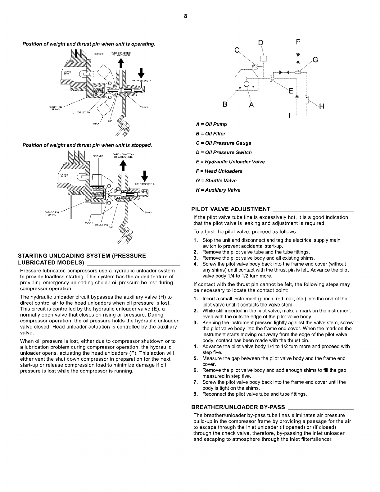
The hydraulic unloader circuit bypasses the auxiliary valve (H) to
direct control air to the head unloaders when oil pressure is lost.
This circuit is controlled by the hydraulic unloader valve (E), a
normally open valve that closes on rising oil pressure. During
compressor operation, the oil pressure holds the hydraulic unloader
valve closed. Head unloader actuation is controlled by the auxiliary
valve.
When oil pressure is lost, either due to compressor shutdown or to
a lubrication problem during compressor operation, the hydraulic
unloader opens, actuating the head unloaders (F). This action will
either vent the shut down compressor in preparation for the next
start-up or release compression load to minimize damage if oil
pressure is lost while the compressor is running.
/
D
\
F
A = Oil Pump
B = Oil Filter
C = Oil Pressure Gauge
D = Oil Pressure Switch
E = Hydraulic Unloader Valve
F = Head Unloaders
G = Shuttle Valve
H = Auxiliary Valve
PILOT VALVE ADJUSTMENT
If the pilot valve tube line is excessively hot, it is a good indication
that the pilot valve is leaking and adjustment is required.
To adjust the pilot valve, proceed as follows:
1. Stop the unit and disconnect and tag the electrical supply main
switch to prevent accidental start-up.
2. Remove the pilot valve tube and the tube fittings.
3. Remove the pilot valve body and all existing shims.
4. Screw the pilot valve body back into the frame end cover (without
any shims) until contact with the thrust pin is felt. Advance the pilot
valve body 1/4 to 1/2 turn more.
If contact with the thrust pin cannot be felt, the following steps may
be necessary to locate the contact point:
1. Insert a small instrument (punch, rod, nail, etc.) into the end of the
pilot valve until it contacts the valve stem.
2. While still inserted in the pilot valve, make a mark on the instrument
even with the outside edge of the pilot valve body.
3. Keeping the instrument pressed lightly against the valve stem, screw
the pilot valve body into the frame end cover. When the mark on the
instrument starts moving out away from the edge of the pilot valve
body, contact has been made with the thrust pin.
4. Advance the pilot valve body 1/4 to 1/2 turn more and proceed with
step five.
5. Measure the gap between the pilot valve body and the frame end
cover.
6. Remove the pilot valve body and add enough shims to fill the gap
measured in step five.
7. Screw the pilot valve body back into the frame end cover until the
body is tight on the shims.
8. Reconnect the pilot valve tube and tube fittings.
BREATHER/UNLOADER BY-PASS
The breather/unloader by-pass tube lines eliminates air pressure
build-up in the compressor frame by providing a passage for the air
to escape through the inlet unloader (if opened) or (if closed)
through the check valve, therefore, by-passing the inlet unloader
and escaping to atmosphere through the inlet filter/silencer.