
Manual


2.
3.
Release any remaining tank pressure by slowly opening the manual
drain valve.
Close the manual drain valve and apply power to the compressor. If
the pressure switch is equipped with an "ON/AUTO-OFF" lever, flip
the switch to the "ON/AUTO" position. If the unit is equipped with a
control panel "ON/OFF" switch, move the switch to the "ON"
position.
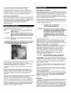
Typical Pressure Switch Lever (if Equipped)
ON/AUTO OFF
4. Slowly open the service valve.
Typical Service Valve (A = Open, B = Closed)
A_.
Z_CAUTION
NOTE
Unusual noise or vibration indicates a problem. Do
not continue to operate until you identify and
correct the source of the problem.
Ensure the direction of rotation is correct per the
arrow on the motor. If the rotation is incorrect on
three-phase units, interchange any two of the three
leads.
START-UP (GASOLINE ENGINE UNITS)
z_ WARNING Do not operate gasoline engine units in an enclosed
area.
1. Release any remaining tank pressure by slowly opening the manual
drain valve.
2. Turn on the engine gasoline supply.
3. Put the choke in the "on" position.
4. Close the service valve and put the unloader lever in the "unload"
(A) position for Kawasaki and Honda engine driven models, or the
"load" (B) position for Kohler engine driven models.
5. Start the engine, release the choke, and allow the engine to warm
up for two to three minutes.
6. Return the unloader lever to the "load" (B) position on Kawasaki and
Honda engine driven models.
Typical Unloader (A = Unload, B = Load)
NOTE
NOTE
Turn the gasoline supply off when the compressor
is not being used.
Some gasoline engine driven compressors require
5-8 break-in hours of operation before reaching full
capacity and speed.
COMPRESSOR CONTROLS
AUTOMATIC START & STOP CONTROL. This type of control
applies to electric motor driven models under 10 horsepower.
NOTE Automatic Start & Stop Control is intended for use
when the motor will start no more than 6 times per
hour.
When the receiver tank pressure reaches the factory pre-set
maximum pressure (usually 175 PSIG), the pressure switch stops
the unit. When the receiver tank pressure drops below the factory
pre-set minimum (usually 135 PSIG), the pressure switch resets
and restarts the unit.
CONSTANT SPEED CONTROL. This type of control applies to
gasoline engine units.
When the receiver tank pressure reaches the factory pre-set
maximum pressure (usually 175 PSIG), the unloader slows down
the engine and the unit stops pumping. When the receiver tank
pressure drops to the factory pre-set minimum (usually 145 PSIG),
the unloader resets, the engine returns to full speed, and the unit
resumes pumping.
DUAL CONTROL. This type of control applies to electric motor
units over 10 horsepower. Select either automatic start and stop
control or constant speed control by adjusting the knob on the
auxiliary valve. For automatic start and stop control, turn the knob
on the auxiliary valve fully clockwise to disable the auxiliary valve.
The pressure switch will then start and stop the unit.
NOTE For dual control models, automatic start and stop is
preferred.
Auxiliary Valve.
KNOB"__
CLOCKWISE
COUNTERCLOCKWISE
Select constant speed control if the unit restarts in less than 10
minute intervals or runs more than 40 minutes per hour. Turn the
knob fully counterclockwise to run the unit continually. When the
receiver tank pressure reaches 170 PSlG, the unit runs but does not
pump.
NOTE The auxiliary valve is factory pre-set at 5 PSIG lower
than the factory pressure switch setting,
A CAUTION Running unloaded for more than 20 minutes per
hour or more than 15 minutes continually with the
use of constant speed control will cause oil
pumping and should be avoided,
PRESSURE SWITCH ADJUSTMENT
z_ WARNING High voltage is present at the pressure switch
contacts when the power supply is connected.
Disconnect, lock and tag main power supply before
making adjustments.
A CAUTION Do not adjust the pressure switch to exceed the
maximum discharge pressure of the unit.
NOTE Adjust the pressure switch only if adjustments are
absolutely necessary.
CUT-IN & CUT-OUT. The cut-out (compressor shut-down) is the
pressure at which the switch contacts open, and the cut-in
(compressor restart) is the pressure at which the switch contacts
close. See COMPRESSOR CONTROLS.
ADJUSTMENT CONTROLS. All pressure switches have a range
adjustment control (A). Some pressure switches also have a
differential adjustment (B) control. On switches without a differential