
Manual


adjustmentcontrol,thespanbetweencut-inandcut-outpressure
levelsswitchesisfactorysetfor40_+4PSIGandcannotbe
adjusted.
NOTE Some pressure switches are equipped with an
on-off lever used to open and close the electrical
contacts inside the switch. THIS LEVER IS NOT A
DIFFERENTIAL ADJUSTMENT CONTROL. The
pressure switches with the on-off lever do not have
a differential adjustment control.
ADJUSTMENT PROCEDURES (SWITCHES WITHOUT
DIFFERENTIAL ADJUSTMENT CONTROL):
1. Remove the pressure switch cover.
2. Adjust the range by turning the range adjustment screw clockwise
(in) to increase the cut-out point or counter-clockwise (out) to
decrease the cut-out point.
NOTE: One full turn changes the setting approximately 2
PSIG.
3. Replace cover, reconnect power supply and start the compressor.
4. Note the pressure gauge reading at which the compressor cuts out.
5. Repeat adjustment procedure if necessary.
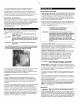
Pressure Switch Range Adjustment.
The oil pump is equipped with an adjustable pressure regulator
which may be reset if conditions warrant. Refer to the following
illustration and instructions:
1. Use an adjustable wrench to remove the knurled cover for the valve
on the right side of the oil pump housing (A).
2. Loosen the retaining nut (B) with a 7/16" wrench such that the
threaded rod (C) is free to rotate.
3. Using a 1/8" hex key, adjust the threaded rod to the desired setting.
Turning the rod clockwise increases the oil pressure setting, and
turning the rod counterclockwise decreases the oil pressure.
4. When the oil pressure is set, tighten the retaining nut and replace
the knurled cover.
ADJUSTMENT PROCEDURES (SWITCHES WITH DIFFERENTIAL
ADJUSTMENT CONTROL):
1. Remove the pressure switch cover.
2. Set the cut-in pressure with the range adjustment nut. Turn the nut
clockwise (in) to increase the pressure or counter-clockwise (out) to
decrease the pressure.
NOTE: One full turn changes the setting approximately 2
PSIG.
3. Set the cut-out pressure with the differential adjustment. Turn the
differential adjustment nut clockwise (in) to increase the pressure or
counter-clockwise (out) to decrease the pressure.
NOTE: One full turn changes the setting approximately 2
PSIG.
4. Replace the cover, reconnect the power supply and start the unit.
5. Note the pressure gauge reading at which the unit cuts out.
6. Repeat the adjustment procedure if necessary.
The minimum possible differential is approximately 20% of cutout
pressure. It is advisable to have as wide a differential as possible to
avoid frequent starting and stopping of the unit. Note the pressure
gauge reading at which the unit cuts-out and re-establish this point
if necessary.
Note the interaction between the range and differential adjustments,
i.e., if the cut-out is increased, the differential will also increase, or
if the differential is narrowed, the cut-out will be reduced, etc. These
factors must be considered when adjusting the switch and
compensated for accordingly.
OIL PRESSURE ADJUSTMENT (MODEL 2000P)
For pressure lubricated compressors, the oil pressure should be
checked upon start-up by observing the oil pressure gauge. The
acceptable operating range is 15-40 psig. It is normal for the oil
pressure to vary slightly with oil temperature. Compressors
equipped with an optional low oil pressure shutdown system will
automatically shut down if the oil pressure drops below 10 psig.
STARTING UNLOADING SYSTEM
The starting unloading feature exists on certain models. The
purpose of the system is to relieve cylinder pressure when the unit
stops, permitting it to start against a light load. A light load
increases the life of the driver and belts and also reduces the
possibility of tripping the overload relay. The system operates in the
following manner:
The centrifugal unloader is attached to the end of the crankshaft as
shown in the following illustrations.
When the unit starts, centrifugal force acts upon the unloader
weights and they swing outward. This permits the plunger and thrust
pin to move inward and the pilot valve to close. The escape path to
atmosphere for the cylinder pressure is now closed and the
compressor pumps air in a normal manner.
When the unit stops, the weights retract, permitting the thrust pin
spring to move the plunger and thrust pin outward. The thrust pin
opens the pilot valve and the trapped air pressure escapes from the
cylinder and intercooler through a passage in the frame end cover,
through the unloader tube and to atmosphere through the inlet
filter/silencer,