IR611-S Industrial Router User Manual InHand Networks www.inhandnetworks.com Version: v1.
Disclaimers The content in this manual is subject to change without notice. This manual is only used as the guidance. InHand makes every effort to provide accurate information in this manual, but InHand does not guarantee that there is no error in the manual. All statements, information and recommendations in this manual do not constitute any expressed or implied warranty. Trademarks and Copyright INHAND, InHand and the InHand logo are trademarks of InHand Networks.
Preface This user manual will guide you on installing and configuring InHand IR6XX-S industrial router. Audience This manual is for: Network Planner Field technical support Network administrators Conventions This manual uses the following conventions: Conventions <> Indication Content in angle brackets “<>” indicates a button name. For example, the button. “” “” indicates a window name or menu name. For example, the pop-up window “New User.
Contents PREFACE .................................................................................................................................................... 2 AUDIENCE ................................................................................................................................................ 2 CONVENTIONS .......................................................................................................................................... 2 CONTENTS ..........................
3.1.4 Admin Access ...................................................................................................................................... 9 3.1.5 System Log ........................................................................................................................................ 11 3.1.6 Configuration Management .............................................................................................................. 12 3.1.7 Task Schedule ..................................
3.4.5 Virtual IP Mapping............................................................................................................................. 31 3.4.6 DMZ ................................................................................................................................................... 31 3.4.7 MAC-IP Binding ................................................................................................................................. 32 3.5 QoS ...................................
Contents I. InRouter6XX-S Introduction 1.1 Overview Integrating 3G, 4G LTE and advanced security, the InRouterXX-S (referred to as “IR6XX-S” thereinafter) series is the next generation of InRouter695 cellular router. With embedded hardware watchdog, link detection, auto-recovery and auto-reboot, the InRouterIR6XX-S series provides reliable communications to unattended sites. Reliable VPN technology secures sensitive data.
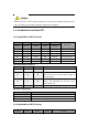
1.2.2 Applicable to IR615-S series Standard Accessories Accessories Quantity Description IR615-S 1 IR615-S series industrial router DIN rail 1 DIN35 rail Power Terminal 1 7PIN 3.81mm industrial terminal Cable 1 1.
IR6XX-S series has a variety of panel appearances, but all of the installation methods are the same. The specific panel condition should be subject to the real object. 1. 4 Introductions to Status LED 1.4.
(Red) (Green) (Yellow) (Red) On Off Off Off Powered On On Blinking On Off Powered on succeed On Blinking On Off Dialing On Blinking Off Off Dialing succeed On Blinking Blinking Blinking Upgrading On Blinking On Blinking Reset Succeed Signal status LED and description: Green LED 1 Green LED 2 Green LED 3 Description Off Off Off No signal detected On Off Off Signal strength 1-9 (Signal strength is weak, please check antenna and the signal strength of current locati
Serial port: At least one Ethernet port: At least one (10M/100M) IE version: Above 5.0 Resolution ratio: Above 640*480 1 SIM card: Ensure the card is enabled with data service and its service is not suspended because of an overdue charge. Power supply: 220V AC: Alternatively used with the product with DC power 9~26V DC: Ripple voltage < 100 mV Fixation: Please place InRouter level and have it installed in an environment with small vibrational frequency.
2.4 Installation of Protective Grounding The specific steps are shown in below: Step 1: Remove the grounding screw. Step 2: Connect the grounding ring of the cabinet’s grounding wire onto the grounding screw. Step 3: Tighten the grounding screw up. To improve the immunity from interference of whole router, the router must be grounded when using. According to operating environment, the ground wire should be connected with grounding stud of router. 2.
If the current supervisory PC uses a proxy server to access the Internet, it is required to cancel the proxy service. The operating steps are shown below: 1) In the browser window, select "tools>>Internet options"; 2) select "connection" page and click the button of LAN Settings to enter "LAN Settings" window interface. Please confirm if the option "Use a Proxy Server for LAN" is checked; if it is checked, please cancel and click the button . IV.
3.1.1 Basic Setup Here, WEB configuration interface language can be set; name of mainframe of router can be customized. From the navigation tree, select System >> Basic Setup, then enter the “Basic Setup” page. Table 3-1-1 Basic Setup Parameters Basic settings Function description: Select display language of the router configuration interface and set personalized name.
Time you may select 1/2/...hours. when startup or very 3.1.3 Serial Port Setting the parameters of router’s serial port according to the serial port of the terminal device connected with router to achieve the normal communication between router and terminal device. From the navigation tree, select System >> Serial Port, then enter “Serial Port” page.
The device supports Telnet Client and Telnet Server. Console The console port, also called the access or serial port, refers for initial configuration and subsequent management of a device. It has the same terminal as the telnet client. From the navigation tree, select System >> Admin Access, then enter “Admin Access” page. Table3-1-4 Parameters of Admin Access Admin Access Function description: 1. Modify username and password of router. 2. The router may be set by the following 4 ways, i.e.
admin functions configuration) Console Login User (Click (without influencing router button after setting a group of username and password) Username Configure console login user, custom N/A Password Configure the password, custom N/A Other Parameters Log Timeout Set login timeout (router will automatically disconnect the configuration interface after login timeout) 500 seconds In “Username/Password” section, users can modify username and password rather than create new username, i.
3.1.6 Configuration Management Here you can back up the configuration parameters, import the desired parameters backup and reset the router. From the navigation tree, select System >> Config Management, then enter the “Config Management” page. Table 3-1-6 Parameters of Configuration Management Configuration Management Function description: Set parameters of configuration management.
From the navigation tree, select System >> Task Schedule, then enter “Task Schedule” page. 3.1.8 System Upgrading The upgrading process can be divided into two steps. In the first step, upgrading files will be written in backup firmware zone, e.g. , the process in the section of System Upgrading; in second step: files in backup firmware zone will be copied to main firmware zone, which should be carried out during system restart.
3. 2 Network Network settings include Dialup/Cellular, WAN (only for IR615-S series), Link Backup, LAN, WLAN Mode Switch, WLAN, DNS, DDNS and Static Routes. 3.2.1 Dialup/Cellular Connection SIM card dial out through dial access to achieve the wireless network connection function of router. Click the “Network>>Dial Interface” menu in the navigation tree to enter the “Dial Interface”.
CARD(China Telecom) Network Type Auto, 2G Only, 3G Only, 4G Only Auto Connection Mode Optional always online, dial on demand, manual dialing Always Online Redial Interval Set the redialing time when login fails. 30 s Show Options Click to show advanced options (parameters of advanced options are listed below) Disable PIN Code For setting PIN code N/A MTU Set max.
PPPoE is a point-to-point protocol over Ethernet. User has to install a PPPoE Client on the basis of original connection way. Through PPPoE, remote access devices could achieve the control and charging of each accessed user. WAN of the device is disabled by default. Click the “Network>>WAN” menu in the navigation tree to enter the “WAN" Interface. Table 3-2-2-1 Static IP Parameters of WAN WAN - Static IP Function description: Wired access to Internet via fixed IP.
Router. Disable—Local device connected to Router cannot access to the Internet via Router. Default route Enable default route Enable MAC Address MAC Address of the device 00:18:05:08:07:3D (provided by InHand Networks), provided for device manufacturer MTU Max. transmission unit, default/manual settings default (1500) Table 3-2-2-3 ADSL Dialing (PPPoE) Parameters of WAN WAN - ADSL Dialing (PPPoE) Function description: Set ADSL dialing parameters.
Enable IP header compression Click to enable IP header compression Disable Use Peer DNS Click to enable use peer DNS Enable Link detection interval Set link detection interval 55 s Link detection Max. Retries Set link detection max.
Here MAC address, IP address and other basic information can be modified and multiple IP access to LAN is supported. Click the “Network>>LAN” menu in the navigation tree to enter the configuration interface. Table3-2-4Parameters of LAN 2 LAN Function description: LAN is the gateway address of router. Parameters Description Default MAC Address MAC Address of the device LAN 00:18:05:08:15:77 (provided by InHand Networks), provided for device manufacturer IP Address Set IP address of LAN 192.168.2.
network devices so that they will have normal network communication. Click the “Network>>WLAN” menu in the navigation tree to enter the “WLAN" interface. Table 3-2-6 Parameters of WLAN Access Port WLAN Function description: Support WiFi function and provide wireless LAN access on site and identity authentication of wireless user. Parameters Description Default SSID broadcast After turning on, use can search the WLAN via SSID name Enable Mode Six type for options: 802. 11g/n, 802. 11g, 802. 11n, 802.
Authentication method Keep consistent with the access point to be connected Open type Encryption Keep consistent with the access point to be connected NONE 3.2.8 DNS DNA (Domain Name System) is a DDB used in TCP/IP application programs, providing switch between domain name and IP address. Through DNS, user could directly use some meaningful domain name which could be memorized easily and DNS Server in network could resolve the domain name into correct IP address.
the application of this function, a domain name shall be applied for and registered on a proper website such as www. 3322. org. IR611-S &IR615-S DDNS service types include QDNS (3322)-Dynamic, QDNS(3322)-Static, DynDNS-Dynamic, DynDNS-Static, DynDNS-Custom and No-IP.com. To set DDNS, click the "Network >> Dynamic Domain Name" menu in the navigation tree, then enter “Dynamic Domain Name” interface.
Static Route Function description: Add/delete additional static rote of router. for users to set it. Parameters Generally, it's unnecessary Description Default Destination Address Set IP address of the destination N/A Subnet Mask Set subnet mask of the destination 255. 255.
automatically, then such service must be activated. Static designation of DHCH allocation could help certain host to obtain specified IP address. Parameters Description Default Enable DHCP Enable DHCP service and dynamically allocate IP address Enable IP Pool Starting Address Set starting IP address of dynamic allocation 192. 2. 2 168. IP Pool Ending Address Set ending IP address of dynamic allocation 192. 2. 100 168.
When enabling DHCP, the DHCP relay is also enabled automatically. Relay cannot be disabled without disabling DHCP. 3.3.3 VRRP: Virtual Router Redundancy Protocol VRRP (Virtual Router Redundancy Protocol) adds a set of routers that can undertake gateway function into a backup group to form a virtual router. The election mechanism of VRRP will decide which router to undertake the forwarding task and the host in LAN is only required to configure the default gateway for the virtual router.
router with highest priority becomes the gateway for the transmission task. From navigation tree, select "Network >>VRRP" menu, then enter “VRRP” page. Table 3-3-3 VRRP Parameters VRRP Function description: Configure parameters of VRRP.
separate multiple numbers Table 3-3-4-2 Device Manager - SMS + IP Parameters Device Manager - SMS + IP Function description: Configuration of device manager functions can connect the router to the device manager. Parameters Description Default Supplier Set name of equipment supplier Default Equipment ID Set ID of router 611341234 Server Set address of device manager server to which the router will access c.inhand.com.
Max. Interval Reconnect Set the max. reconnect interval 180 s DTU ID Set DTU ID. N/A Source address Set the Source IP. N/A Report DTU ID interval Set report of DTU ID interval 0s Multi-Server Set server address and port N/A 3.3.6 SMS SMS permits message-based reboot and manual dialing. Configure Permit to Phone Number and click .
3.4.1 Basic Setup From the navigation tree, select Firewall >> Basic Setup, then enter the “Basic Setup” page. Table 3-4-1 Firewall - Basic Setup Parameters Basic Setup of Firewall Function description: Set basic firewall rules.
Log Click to enable log and the log about access control will be recorded in the system. Disable Description Convenient for recording parameters of access control N/A 3.4.3 Filtering Configuration of mapping rules is generally used to disable access to network settings. From navigation tree, select "Firewall>>Filtering" menu, then enter “Filtering” page.
External (optional) address Description Set external address/tunnel name of port mapping N/A For recording significance of each port mapping rule N/A 3.4.5 Virtual IP Mapping Both router and the IP address of the host of intranet can correspond with one virtual IP. Without changing IP allocation of intranet, the extranet can access to the host of intranet via virtual IP. This is always used with VPN.
The IR6x1's management port should never be mapped to the device port by this function. 3.4.7 MAC-IP Binding If the default process in the basic setting of firewall is disabled, only hosts specified in MAC-IP can have an access to outer net. From the navigation tree, select Firewall >> MAC-IP Binding, then enter the “MAC-IP Binding” page. Table 3-4-7 Firewall - MAC-IP Binding Parameters MAC-IP Binding (at most 20 MAC-IP Bindings can be set) Function description: Configure MAC-IP parameters.
From the navigation tree, select QoS >> Bandwidth Control, then enter the “Bandwidth Control” page. Table 3-5-1 Parameters of Bandwidth Control Bandwidth Control Function description: Configure bandwidth control. Parameters Description Enable Outbound Bandwidth Inbound Bandwidth Limit: Limit: Max. Max. Default Click to enable the function of bandwidth control Disable Set the maximum upload bandwidth. 100000kbit/s Set the maximum download bandwidth. 100000kbit/s 3.5.
meanwhile can be used by unauthorized VPN users so that what VPN users obtained is only a logistic private network. This public network is regarded as VPN Backbone. Build a credible and secure link by connecting remote users, company branches, partners to the network of the headquarters via VPN so as to realize secure transmission of data.
dangers such as password and bank account information stolen and tampered, user identity imitated, suffering from malicious network attack, etc. After disposal of IPSec on the network, it can protect data transmission and reduce risk of information disclosure.
Parameters Click to options Show Advanced Options Description Default enable Disable (open advanced options after enabling) advanced Basic parameters Tunnel Name User defines tunnel name IPSec_tunnel_1 Destination Address Set destination IP address or domain name 0.
username XATUTH password User defines password XATUTH MODECFG Click to enable MODECFG N/A Disable Phase II Parameters IPSec Strategy Multiple strategies available 3DES-MD5-96 IPSec Life Cycle Set IPSec life cycle 3600 s Perfect Forward Secrecy (PFS) (Advanced Option) Select disable/Group 1/Group 2/Group 5 Disable (this needs to match the server) Link Detection Parameters (Advanced Option) DPD Interval Set time interval. 60 s DPD Timeout Set the timeout for dropped packets.
X Network X Network GRE Tunnel Along with the extensive application of IPv4, to have messages from some network layer protocol transmitted on IPv4 network, those messages could by encapsulated by GRE to solve the transmission problems between different networks. In following circumstances GRE tunnel transmission is applied: GRE tunnel could transmit multicast data packets as if it were a true network interface. Single use of IPSec cannot achieve the encryption of multicast.
Enable Click to enable GRE Enable Name User defines name of GRE tunnel tun0 Local visual IP Set local virtual IP 0. 0. 0. 0 Destination Address Set remote IP address 0. 0. 0. 0 Peer visual IP Set peer virtual IP 0. 0. 0. 0 Peer Subnet Address Set peer subnet IP address 0. 0. 0. 0 Peer Subnet Mask Set remote netmask 255. 255.
RADIUS Server RADIUS Server Enterprise Branch Enterprise Headquarter L2TP Tunnel Dialling User L2TP Tunnel Mobile Office Staff (L2TP Dialling Software) From navigation tree, select VPN>>L2TP Client, enter "L2TP Client" and click . Table 3-6-4 Parameters of L2TP Client 3 L2TP Client Function description: Configure parameters of L2TP client.
Expert Option recommended) (not Set expert option, not recommended N/A 3.6.5 PPTP Client From navigation tree, select VPN>>PPTP Client, enter "PPTP Client" and click . Table 3-6-5 Parameters of PPTP Client 4 PPTP Client Function description: Configure parameters of PPTP client.
SSLv3/TLSv1 protocol are massively used. In OpenVPN, if a user needs to access to a remote virtual address (address family matching virtual network card), then OS will send the data packet (TUN mode) or data frame (TAP mode) to the visual network card through routing mechanism.
Expert Option recommended) (not Set expert option, not recommended N/A 3.6.7 OpenVPN Advanced From navigation tree, select "VPN>>OpenVPN Advanced" and enter "OpenVPN Advanced" interface. Table 3-6-7 Configuration Parameters of OpenVPN Advanced OpenVPN Advanced Function description: Configure parameters of OpenVPN Advanced.
cannot be changed an enrollment Server URL Set server URL N/A Common Name Set common name N/A FQDN Set FQDN N/A Unit 1 Set unit 1 N/A Unit 2 Set unit 2 N/A Domain Set domain N/A Serial Number Set serial number N/A Challenge Set challenge N/A Challenge Confirm Challenge confirm N/A Protect Key Set protect key N/A Protect Key Confirm Confirm protect key N/A Unstructured address Set unstructured address N/A RSA Key Length Set RSA key length 1024 Poll Interval Set poll
“Traceroute” page. Table 3-7-2 Traceroute Parameters Traceroute Function description: Applied for network routing failures detection. Parameters Description Default Host Address of the destination host which to be detected is required. N/A Max. Hops Set the max. hops for traceroute 20 Timeout Set the timeout of traceroute 3s Protocol ICMP/UDP UDP Expert Option Advanced parameter for traceroute is available. N/A 3.7.
3.8.3 Network Connections From navigation tree, select Status >> Network Connections, then enter “Network Connections” page to see the connections status. This page shows the basis information of dialup and LAN. Dialup includes connection type, IP address, netmask, gateway, DNS, MTU, status and connection time. LAN includes MAC address, IP address, netmask, gateway, MTU and DNS. 3.8.4 Route Table From navigation tree, select Status >> Route Table, then enter “Route Table” page to see router status.
Appendix A FAQ 1. InRouter is powered on, but can't access Internet through it? Please first check: Whether the InRouter is inserted with a SIM card. Whether the SIM card is enabled with data service, whether the service of the SIM card is suspended because of an overdue charge. Whether the dialup parameters, e.g. APN, dialup number, username and password are correctly configured.
server, but the center can't connect to your PC under InRouter? Please make sure the firewall of your computer is disabled. 7. After InRouter establishes VPN with the VPN server, your PC under InRouter can't connect to the server ping? Please make sure “Shared Connection” on “Network=>WAN” or “Network=>Dialup” is enabled in the configuration of InRouter. 8. InRouter is powered on, but the Power LED is not on? Check if the protective tube is burn out.
settings. Appendix B Instruction of Command Line 1Help Command Help command can be obtained after entering help or “?” into console, “?” can be entered at any time during the process of command input to obtain the current command or help from command parameters, and command or parameters can be automatically complemented in case of only command or command parameter. 1.1 Help [Command] Help [] [Function] Get help from command.
inputting will be given in case of no entering. [Example] Enter exit in ordinary user view: enable 123456 Switchover to super users and the password 123456. 2.2 Disable [Command] Disable [Function] Exit the privileged user level. [View] Super user view, configure view [Parameter] No [Example] Enter in super user view: disable Return to ordinary user view. 2. 3 End and ! [Command] End or ! [Function] Exit the current view and return to the last view. [View] Configure view.
Enter in configured view: exit Return to super user view. enter exit in ordinary user view: exit Exit console. 3 Check system state command 3. 1 Show version [Command] Show version [Function] Display the type and version of software of router [View] All views [Parameter] No [Example] Enter: show version Display the following information: Type : display the current factory type of equipment Serial number : display the current factory serial number of equipment Description : www.inhand.com.
Example: 00:00:38 up 0 min, load average: 3. 3 show clock [Command] Show clock [Function] Display the system time of router [View] All views [Parameter] No [Example] Enter: show clock Display the following information: For example Sat Jan 1 00:01:28 UTC 2000 3.
[Function] Display the log of router system and display the latest 100 logs in default. [View] All views [Parameter] Lines limits the log numbers displayed, wherein, n indicates the latest n logs in case that it is positive integer and indicates the earliest n logs in case that it is negative integer and indicates all the logs in case that it is 0. [Example] Enter: show log Display the latest 100 log records. 3. 6 Show users [Command] Show users [Function] Display the user list of router.
Enter: show startup-config Display the starting configuration of system. 3. 8 Show running-config [Command] Show running-config [Function] Display the operational configuration of router [View] Super user view and configuration view [Parameter] No [Example] Enter: show startup-config Display the operational configuration of system. 4 Check Network Status Command 4.
Display system ip status 4. 3 Show route [Command] Show route [Function] Display the routing list of router [View] All views [Parameter] No [Example] enter: show route Display the routing list of system 4. 4 Show arp [Command] Show arp [Function] Display the ARP list of router [View] All views [Parameter] No [Example] Enter: show arp Display the ARP list of system 5 Internet Testing Command Router has provided ping , telnet and traceroute for Internet testing. 5.
[Example] Enter: ping www.g.cn Test www. g. cn and display the testing results 5. 2 Telnet [Command] Telnet [] [source ] [Function] Telnet logs in the appointed mainframe [View] All views [Parameter] in need of the address or domain name of mainframe logged in. telnet port source appoints the IP address of telnet logged in. [Example] Enter: telnet 192.168.2.2 telnet logs in 192. 168. 2. 2 5.
management. Some setting command can support no and default, wherein, no indicates the setting of canceling some parameter and default indicates the recovery of default setting of some parameter. 6. 1 Configure [Command] Configure terminal [Function] Switchover to configuration view and input the equipment at the terminal end. [View] Super user view [Parameter] No [Example] Enter in super user view: configure terminal Switchover to configuration view. 6.
[Command] Clock timezone default clock timezone [Function] Set the time zone information of the router. [View] Configure view. [Parameter] timezone name, 3 capitalized English letters time zone deviation value, -12~+12 [Example] Enter in configured view: clock timezone CST -8 The time zone of IG601is east eighth area and the name is CST (China's standard time). Enter in configured view: default clock timezone Recover the timezone of router to the factory setting. 6.
[Function] Set the customer end of Internet time server [View] Configure view. [Parameter] address or domain name of mainframe of time server [Example] Enter in configured view: ntp server pool.ntp.org Set the address of Internet time server pool. ntp. org. Enter in configured view: no ntp server Disable the router to get system time via network. Enter in configured view: default ntp server Recover the network time server of router to the factory setting. 6.
The config. is imported. 7 System Management Command 7. 1 Reboot [Command] Reboot [Function] System restarts. [View] Super user view and configuration view [Parameter] No [Example] Enter in super user view: reboot System restarts. 7. 2 Enable username [Command] Enable password [] [Function] Modify the username of super user. [View] Configure view. [Parameter] new super user username [Example] Enter in configured view: enable username admin The username of super user is changed to admin. 7.
Enter password according to the hint. 7. 4 Username [Command] Username [password []] no username default username [Function] Set user name, password [View] Configure view. [Parameter] No [Example] Enter in configured view: username abc password 123 Add an ordinary user, the name is abc and the password is 123. Enter in configured view: no username abc Delete the ordinary user with the name of abc. Enter in configured view: default username Delete all the ordinary users.
FCC STATEMENT 1. This device complies with Part 15 of the FCC Rules. Operation is subject to the following two conditions: (1) This device may not cause harmful interference. (2) This device must accept any interference received, including interference that may cause undesired operation. 2. Changes or modifications not expressly approved by the party responsible for compliance could void the user's authority to operate the equipment.
IC STATEMENT La operación de este equipo está sujeta a las siguientes doscondiciones: (1) es posible que este equipo o dispositivo nocause interferencia perjudicial y (2) este equipo o dispositivodebe aceptar cualquier interferencia, incluyendo la que pueda causar su operación no deseada. This radio transmitter (11594A-IR611S) has been approved by Industry Canada to operate with the antenna types listed below with the maximum permissible gain indicated.
fonctionner avec les types d'antenne énumérés ci-dessous et ayant un gain admissible maximal. Les types d'antenne non inclus dans cette liste, et dont le gain est supérieur au gain maximal indiqué, sont strictement interdits pour l'exploitation de l'émetteur. types d'antenne: WIFI: Reverse SMA 4G: SMA-J Gain:2.5dBi Gain:2.