
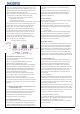
User Guide


Please refer to the input sensor reference table to select sensor type and set
the code. The default setting of sensor type is type K thermocouple. If other type
6.1 Display status
sensor was adopted, it’s a must to reset the configuration. After power on, the instrument will conduct self-tuning, then enter measuring
If error occurred when some thermocouples are used in different environments, and monitoring status automatically. PV window displays current measured
press SC to calibrate as per the detailed stipulation in this manual. value, while SV window displays setting value; If “orAL” was displayed
alternately between PV and SV windows, it means input value exceeded
measuring range (or sensors in open loop), or input setting is incorrect.
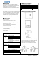
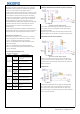
#3 and #4 terminals are for connecting thermocouple. No inverse connection of When there was alarm output, SV window will alternately display characters
positive pole and negative pole are allowed. For common thermocouples, positive
related to the alarms:
pole is red, while negative pole is blue or green. If the poles were connected HiAL(alarm for high limit),LoAL(Alarm for low limit),
inversely, the measured value will be displayed inversely on the screen. dHAL(alarm for plus deviation),dLAL(alarm for minus deviation).
6.2 View output value
#3 and #4 terminals are the input ports for dual lines PT100 sensor, at the same Press “SET” key (no longer than 1 second), if SV window displays character
time #4 and #5 terminals should be connected together. “A”(for instance), it indicates automatic control mode, while if the displayed
character is “M” (for instance: ), it indicates the manual control mode.
When connecting three lines RTD sensor, #3 terminal is for red wire, #4 and #5
are for other two blue lines. For some sensors, #4 and #5 terminals should be
6.3 Automatic/Manual control switch
connected together. Press “«” key (no longer than 1 second), the temperature controller can
switch between automatic and manual control mode without interference to
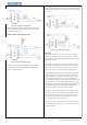
#9 and #10 terminals are for connecting power supply, polarity is indifferent when the operation. Under automatic control mode, RUN indicating light will off;
connecting. Before installation, it’s a must to confirm the compliance of the input and under manual control mode, RUN indicating light will on.
voltage to product specification, otherwise, there will be risks of abnormal usage, (remarks: if the running status of the function setting is “2: forbid manual
electric shock and fire. mode”, above operation is invalid).
4.3.1 The output driving voltage and current of Model ITC-100V are 12VDC and
30mA respectively, while #6 output terminal is for negative pole, and #8 terminal
6.4 Value setting
is for positive pole. It can drive SSR (Solid-state replay). Please note that the
When SV window displays setting value, press “︽” key (“︾” key) to increase
positive pole and negative pole shouldn’t be connected inversely. (decrease) setting value. Press “«” key to move cursor to required numerical
4.3.2 Model ITC-100R output relay control signals. COM7 is public port,
position. Keeping “︽” key or “︾” key to be pressed could increase or
COM6(NC) is normally closed, COM8 (NO) is normally opened. It could directly decrease the value quickly.
control load of AC250V, <3A; for controlling load of AC250V, >3A, external high
capacity controller is needed.
6.5 Launch self-tuning function
When use the instrument for the first time, it’s a must to use the self-tuning
Alarm is controlled by relay signals. COM12 (COM) is public port, COM1 is function of the instrument to determine control parameters (M50, P and t)
normally closed, COM11 is normally opened, maximum load is AC250/3A for an ideal control effect. Press “«” key for over 2 seconds, then the SV
(resistive load). window will display characters “A” and “T” alternately, and the system will
enter self-tuning mode. When self-tuning, the temperature controller will
conduct digital adjustment. After oscillation for 2 to 5 times, the instrument
will automatically set the PID control parameters (parameters M50, P and T).
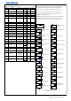
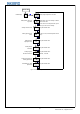
PV window displays
After self-tuning, the system will return to PID automatic control mode.
measured value or set functional symbols
During self-tuning, press “«” key for over 2 seconds to cancel self-tuning,
SV window displays then the characters “AT” displayed in SV window will disappear.
setting value or set value to be read
Attentions: for temperature controller which had run self-tuning before,
Working indicating light
it’s a must to set parameter CtrL as “2” before launching another self-tuning
OUT: Indicating control signal output
(please refer to section “parameters setting and definition” in this manual
AL1: Indicating AL1 alarm
for detailed operation). The control parameter value will vary according to
AL2: Indicating AL2 alarm
setting temperature, therefore, it’s a must to run self-tuning with the most
RUN: Manual indication
frequently used setting value of the system. If the setting value often
“INCREASE” key: when setting value, press“︽” key to increase changes, run self-tuning with the middle value of setting values.
value, keeping this key to be pressed can increase value quickly.
“DECREASE”key: when setting value, press “︾” key to decrease
value, keeping this key to be pressed can decrease value quickly.
“MOVE“ key: when setting temperature value or parameters,
use this key to move cursor to required numerical position.
“SELF-TUNING” key: when in normal display mode, long
press this key for over 2 seconds to start or stop self-tuning.
“SWITCHING” key: when in normal display mode, press this
key for less than 1 second to switch automatic and manual mode.
“SET” key: when in normal display mode, press this key to view setting value for control
signal output; long press for over 2 seconds to enter parameters setting mode.
6. Operation instruction
4.4 Connection for alarm control
Figure 5
4.1 Connecting sensors
4.1.2 Dual lines PT100 sensor
5. Panel instruction
4.3 Connection for control signal output
4.2 Power supply connection
4.1.3 RTD sensor
4.1.1 Thermocouple
3
© 2015 Inkbird Inc. All rights reserved.
www.ink-bird.com, CS@ink-bird.com