
User Guide

6.8 Parameters related to alarm output: “HiAL, LoAL, dHAL, dLAL、
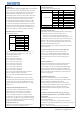
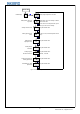
6.9 Parameters related to input “ Sn, diP, diL, diH, DL, Sc”
dF, ALP, CF” 6.9.1 Sensor type input “Sn”
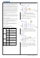
6.8.1 Alarm parameters: "HiAL、LoAL、dHAL、dLAL". These parameters
Table 4: sensor input code and measuring range
are for setting the alarm function of the instrument. When there is alarm
condition, the system will output alarm signals to drive alarm relay to act
(normally opened contact close/normally closed contact open), and
alternately display the alarm reasons in the bottom screen. The alarm will
be dismissed once the fault is fixed. Alarm conditions are as following:
HiAL: alarm when measured value is larger than HiAL (PV>HiAL).
LoAL: alarm when measured value is smaller than LoAL (PV<LoAL).
dHAL: alarm when plus deviation is larger than dHAL (PV>SV+dHAL).
dLAL: alarm when minus deviation is smaller than dLAL (PV<SV-dLAL).
Generally, user don’t need 4 alarms in effect at the same time. For any
alarm not required, set it to the maximum value to avoid triggering it. For
example, set HiAL=9999, LoAL=-1999, dHAL=9999, or dLAL=9999.
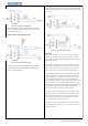
6.9.2 Decimal point position “diP”
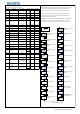
6.8.2 Defining parameter for alarm"ALP"
Decimal position “diP” is for selecting displaying accuracy. This setting is only
Table 3: defining alarm function
for display. The internal measuring accuracy is fixed to be 0.1℃.
When diP=0, it means the temperature display accuracy is 1℃.
When diP=1, 2 or 3, it means the temperature display accuracy is 0.1℃.
When the temperature display accuracy is set to be 0.1℃, while the measured
temperature is lower than 1,000℃, the temperature will be displayed with
accuracy 0.1℃; when the measured temperature is higher than 1,000℃, the
temperature will be displayed with accuracy 1℃.
Changing diP parameter can only influence the display, there is no influence to
the measuring accuracy.
6.9.3 Definition parameters "diH" and "diL" for linear input range
Above are part of common ALP setting. The setting range is 0 - 31. Linear input includes signals such as current: 0-20mV, 0-60mV;
It defines the output position of 4 alarms -- HiAL、LoAL、dHAL、
voltage: 0-1V, 0-5V; resistance: 0-80Ω, 0-400Ω. The displaying value
dHAL. It’s defined by following formula: range for the signals is -1999 - 9999 (decimal position could be set by
ALP=A×1+B×2+C×4+D×8+E×16 diP). Parameters diH and diL are used to define the display range of
When A=0, HiAL alarm is output by AL1; linear input.
When A=2, HiAL alarm is output by AL2;
When B=0, LoAL alarm is output by AL1;
6.9.4 Filtering parameter “dL”
When B=2, LoAL alarm is output by AL2; ITC-100 has in-built digital filtering system. When the displayed value is
When C=0, dHAL alarm is output by AL1; not stable due to input interference, use digital filtering to smooth it.
When C=1, dHAL alarm is output by AL2; dL=0-20, the larger the dL value, the measured value will be more stable,
When D=0, dHAL alarm is output by AL1; but respond will be more dull. When the instrument is interfered at field,
When D=1, dHAL alarm is output by AL2; gradually increase the dL value till the instant variation of measured value
When E=0, SV screen will display alternately the alarm symbols, is within 2-5 unit. When verifying the instrument, it’s a must to set dL as 0
enabling user to know the reasons for alarm quickly; to improve responding speed.
When E=1, SV screen won’t display alternately the alarm symbols
(except orAL)
6.9.5 Amendment parameter “Sc”
Alarm for input exceed measurable range (orAL) could occur when
Parameter “Sc” is for offset amendment for input to compensate the
there are improper sensor specification setting, input disconnected or deviation of sensor or input signal. For thermocouples, if there is deviation
short circuit. If such alarm occurred, the instrument will stop control, at the cold compensation, use parameter “Sc” to amend.
and keep the output value as stipulated by parameter oPL. No setting
For example, assume input signal is constant (500℃), and Sc value is
is needed for orAL.
0.0℃, then the measured temperature is 500.0℃; while Sc value is 10.0℃,
the measured temperature is 510.0℃. The default value of Sc is 0.
6.8.3 Hysteresis Band (Dead Band) parameter "dF"
This parameter shouldn’t be amended unless there is need to calibrate
For avoiding alarm signals caused by input value fluctuation, and the measurement.
consequently malfunction, the instrument has return difference
parameter dF (also called as non-sensitive zone, dead zone, or
6.10 Parameters related to control output “oPI、oPL、oPH、CtrL”
hysteresis). For example, the influence of dF parameter: assume
6.10.1 Output mode parameters "oPI", "oPL" and "oPH" are used for
HiAL value is 800 ℃, dF value is 2.0℃, then only when the measured
limiting output
temperature is larger than 802℃(HiAL+dF), the instrument enters HiAL
oPI is the mode of main output signal; oPL and oPH are the output low
alarm status. And only when the measured temperature is lesser than limit and high limit respectively.
798℃(HiAL-dF), the alarm will be dismissed.
When oPI=0, main output mode is time proportioning output (professional
6.8.4 Function parameter "CF"
PID adjustment) or digital adjustment. Models with SSR, relay, and zero-crossing
Parameter CF is for selecting some system functions: when CF=2, triggering silicon should set oPI=0.
it’s heating control; when CF=3, it’s refrigeration control. When oPI=1, output mode is continuous output (for models with linear
Lower alarm limit
0
Pt100
Cu50
0~1000ºC
0~1000ºC
0~1800ºC
0~1300ºC
J
T
7
20
B
N
E
Input
21
WRe
Code
0
Sensor type
thermocouple
Copper resistor
6
4
5
K
S
Alarm output
Alarm type
ALP
Upper alarm limit
0
Platinum resistor
Deviation low alarm
8
AL2
Deviation high alarm
0
Deviation low alarm
0
Upper alarm limit
1
Lower alarm limit
Deviation high alarm
4
2
AL1
1
2
3
Measuring range
-50~1300ºC
-50~1700ºC
-0~2300ºC
-2000~350ºC
-50~150ºC
-200~600ºC
5
© 2015 Inkbird Inc. All rights reserved.
www.ink-bird.com, CS@ink-bird.com