
User Guide

6.13 Field parameter "EP1 - EP8"
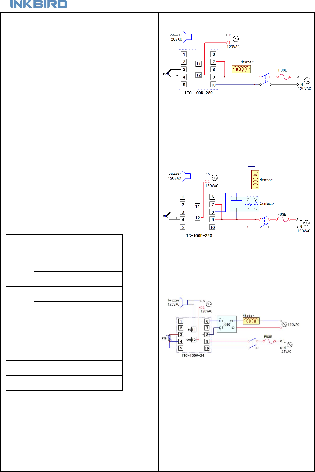
7. Wiring instruction
After setting the instrument, most parameters don’t need to be amended
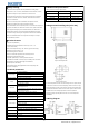
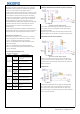
7.1 Directly control load by the internal relay of the instrument.
at field. Besides, operators generally don’t understand many parameters,
and there is risk of fault caused by wrong setting by operators.
Generally, intelligent instrument has parameter lock (Loc) function. Common
parameter lock will lock all the parameters. Sometimes, certain parameters
need to be amended or adjusted at field by the operators. For example,
parameters such as alarm high limit or alarm low limit. In parameter table,
EP1 - EP 8 are 8 field parameters for operators. The value of parameter
EP is other parameters, such as HiAL and LoAL. When Loc=0 or 1,
selected parameters will be displayed, other parameters won’t be displayed
and amended. This function can speed up the amendment, and avoid
important parameters (such as input and output parameters) been
amended incorrectly. Control the heater by the internal relay of the instrument, no external control
There are maximum 8 field parameters available for parameter EP1- EP2. circuit is needed. This mode is only applicable for heater whose maximum
If field parameters are less than 8 (sometime none), they should be defined load is 250V/3A or 120V/6A.
orderly from EP1 to EP8. Vacant field parameters are defined as nonE. The internal control of alarm is relay output control which controls the power
supply of the speaker. User can use bulb to replace with the speaker as alarm.
6.14 Permission for parameters “Loc”
Protection function Loc: when Loc is set as value except 2, 40, 808, the
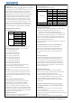
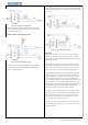
7.2 Control the load via external contactor
instrument only display the filed parameters (EP1 - EP8) and Loc. Only if
set Loc as 2, 40 or 808, all the parameters can be amended.
When Loc=0, field parameters (EP1 - EP8)and temperature setting
value can be amended.
When Loc=1, field parameters can’t be amended (except Loc).
When Loc=2, 40 or 808, all the parameters and temperature setting
value can be amended.
6.15 Common faults and handling methods
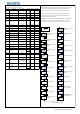
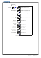
Table 5:Error and handling
Instrument control output via external relay or contactor. With this method,
the user can select external relay or contactor based on the power of heater,
avoid output limitation of the internal relay of the instrument, and improve the
lifetime of the instrument.
7.3 SSR control
ITC-100VH’s output control signal is DC12V voltage for controlling external
SSR to control the heater. User can select SSR based on the power of the
heater. SSR is a kind of electronic switch without contactor, which can be
used for higher frequency control than relay, featuring more stable temperature
control for heater and long lifetime.
orAL displayed
on the
instrument
Sensor fault
Check whether sensor is connected
correctly
Malfunction of
relay
Wrong setting
for control
output
Figure 8:ITC-100RH Wiring diagram
Figure 10:ITC-100VH Wiring diagram
Faults
Figure 9:ITC-100RH Wiring diagram
Power cable is
not well
connected
Check whether the power cable is
bad or wrongly connected
Instrument fault
Contact manufacturer or dealer
Wrong
measured value
Wrong
graduation
mark selected
Select correct graduation mark in
accordance with input signal
Wrong
connection for
sensors
Connect signal cable correctly
Reasons
Handling methods
PV and SV
screen not work
Wrong input
voltage
Check whether the input voltage is in
accordance with the specification of
the instrument
Refer to the alarm instruction in the
user manual to selected required
alarm mode
No control
output
Wrong wiring
for control
output
Connect control output cable
correctly
Wrong
graduation
mark selected
Select correct graduation mark in
accordance with input signal
Wrong
connection for
sensors
Connect signal cable correctly
7
© 2015 Inkbird Inc. All rights reserved.
www.ink-bird.com, CS@ink-bird.com