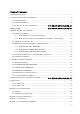
1. Installation F low C hart...................................... ................................................................ 7 2. C omponent Verific ation and Explanation............................................................................. 8 2.1 DONOR UNIT(DU) .............................................. ...................................................... 9 2.2 C OVERAGE UNIT(C U) ........................................... ........................................... Fig. 1 Installation Flow Chart .................................................................................................................................... 7 Fig. 2 List of all the Componants in the System ................................... 오류! 책갈피가 정의되어 있지 않습니다. Fig. 3 Additional CU Componants......................................................... 오류! 책갈피가 정의되어 있지 않습니다. Fig. 4 DONOR UNIT(DU) Image .......................................................... 오류! 책갈피가 정의되어 있지 않습니다. Fig.
Table 1 Band Setting ................................................................................................................................................. 14 Table 2 Cellular Frequency ...................................................................................................................................... 34 Table 3 PCS Frequency.............................................................................................................................................
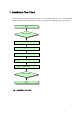
1. Installation F low C hart This doc ument will provide details on how to suc c essfully install the J uni J R- 20 Repeater system. The flow c hart below provides a step by step guide for installing the J R- 20 Repeater 1. S tart 2. Package C heck 3. Loc ating 4. Band S etting 5. DU 6. C U 7. Power / Optimization 8. S tatus C hec k 9. End F ig.
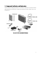
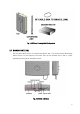
2. C omponent Verific ation and Explanation The first step when installing the repeater is to c hec k that all c omponents are present and that the parts do not have any visible faults. The figure below illustrates the items inc luded in the J uni J R20 Repeater Kit. F ig.
F ig. 3 Additional C overage Unit C omponents 2.1 DONOR UNIT(DU) The role of the Donor Unit is to c ommunic ate with the BTS . It is loc ated outside the building where servic e is to be improved. The Donor Unit c an be mounted onto a wall or a pole, depending on the spec ific installation needs. F ig.
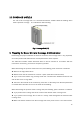
2.2 C OVERAGE UNIT(C U) The role of the C overage Unit is to c ommunic ate with the mobiles within the building whic h needs improved c overage. It is intended for wall mounting. F ig. 5 C overage Unit (C U) 3. Preparing for Donor Unit and C overage Unit Installation Determining the proper installation loc ation for the Donor and C overage Units is very important, sinc e their position will determine the overall performanc e of the repeater.
4. BAND S ETTING Onc e the planning of the loc ation and positioning of the Donor and C overage Units is finalized, the authorized installer should proc eed with installing the Donor and C overage Units. But first, the installer should set the appropriate frequenc y band(s) for the repeater. The figure and table below show the DIP S witc h and the func tions for eac h sec tion. Usually both the PC S and C ellular bands have to be set up. After DIP S /W setting, turn power ON/OF F or DIP S /W 12# PIN ON/OFF.
BW UP LINK DOWN LINK DIP S WITC H REMARK White ON 1850 ~ 1855 1930 ~ 1935 1 2 3 4 5 6 7 8 9 10 11 12 c olor is switc h.
ON 1860 ~ 1870 1940 ~ 1950 1 2 3 4 5 6 7 8 9 10 11 12 7 8 9 10 11 12 ON 1865 ~ 1875 1945 ~ 1955 1 2 3 4 5 6 ON 1870 ~ 1880 1950 ~ 1960 1 2 3 4 5 6 7 8 9 10 11 12 3 4 5 6 7 8 9 10 11 12 3 4 5 6 7 8 9 10 11 12 3 4 5 6 7 8 9 10 11 12 3 4 5 6 7 8 9 10 11 12 3 4 5 6 7 8 9 10 11 12 3 4 5 6 ON 1875 ~ 1885 1955 ~ 1965 1 2 ON 1880 ~ 1890 1960 ~ 1970 1 2 ON 1885 ~ 1895 1965 ~ 1975 1 2 ON 1890 ~ 1900 1970 ~ 1980 1 2 ON 1895 ~ 1905 1975 ~ 1985 1 2 ON 1900 ~ 1910 1980 ~ 1990 1 2
ON 1880 ~ 1895 1960 ~ 1975 1 2 3 4 5 6 7 8 9 10 11 12 3 4 5 6 7 8 9 10 11 12 3 4 5 6 7 8 9 10 11 12 3 4 5 6 7 8 9 10 11 12 ON 1885 ~ 1900 1965 ~ 1980 1 2 ON 1890 ~ 1905 1970 ~ 1985 1 2 ON 1895 ~ 1910 1975 ~ 1990 1 2 Table 1 Band S etting 14
5. DONOR UNIT(DU) S ET Installation 5.1 BRAC KET- DU Image 5.1.1. DU 에 BRAC KET – DU C onnec tion Image 1) The length unit is [ mm] . F ig. 7 MTG Brac ket Image 5.1.2. BRAC KET- DU C onnec tion Image to Installation(WALL or POLE) ( Pole Mounting ) ( Lumber Wall Mounting) ( C onc rete Wall Mounting ) F ig.
5.2 BRAC KET C onnec tion to DU 1) 1) APPLY NUT, S PRING WAS HER, PLATE WAS HER. (Do not C onnec t C ompletely) [ NUT, S PRING WAS HER, PLATE WAS HER eac h 4ea] 2) Apply BRAC KET/MTG to DU. APPLY NUT C OMPLETELY US ING PROVIDED TOOL. [ BRAC KER/MTG 1ea] F ig.
5.3 BRAC KET C onnec tion depending on Installation Plac e 5.3.1. BRAC KE T/MTG POLE MOUNTING 1) S ec ure DU to the pole using U- BOLT. 2) Insert U- BOLT to between BRAC KET- POLE and BRAC KET- DU 3) Apply the pole to the BRAC KET- DU: use the nuts and u- bolts provided to fixate the brac ket into the Pole. [ BRAC KET- DU 1ea, BRAC KET- POLE 2ea, U- Bolt 2ea, NUT, S PRING WAS HE R, PLATE WAS HER eac h 4ea] F ig. 10 POLE MOUNTING MTG BRAC KET- DU C onnec tion S equenc e 5.3.2.
5.3.3. BRAC KET/MTG C ONC RETE WALL Mounting 1) Drill on the wall as the BRAC KET- ANT distanc e. (forφ 10mm Hole depth to be 30 to 40 mm.) 2) INS ERT S ET- ANC HOR TO DRILLED HOLE. 3) S ec ure BRAC KET- DU to the Wall and fix the nut. [ BRAC KER- DU 1ea, S ET- ANC HOR 4ea] F ig. 12 C ONC RETE WALL MOUNTING MTG BRAC KET- DU C onnec tion S equenc e 5.4 DU C onnec tion (same as 5.1) with BRAC KET(same as 5.2) 1) APPLY DU to the BRAC KET. 2) Apply the NUT to the upside of BRAC KET like below sequenc e.
c ompletely. 3) S et the rec eiving direc tion of the ANTENNA and apply the NUT c ompletely using the provided tool. [ NUT, S PRING WAS HER, PLATE WAS HER eac h 4ea] F ig.
5.5 Installation C ompletion. F ig. 14 DU Unit POLE Mounting Installation C ompletion Diagram F ig. 15 DU Unit LUMBER WALL Mounting Installation C ompletion Diagram F ig.
6. C U Wall & C eil Mount Installation 6.1. MTG Brac ket Image F ig.
6.2 GYPS UM BOARD WALL MOUNTING 1) S ec ure DRYWALL anc hor to the GYPS UM BOARD WALL using c ross driver by keeping BRAC KET Hole distanc e 5.5inc h(140mm). 2) S ec ure DRYWALL anc hor sc rew(TS _1 TH+ 4x16L) to BRAC KET/install. F ig. 18 C U Brac ket Gypsum Wall Mounting 6.3 C ONC RETE WALL MOUNTING 1) S ec ure PLAS TIC ANC HOR TO WALL. : INS ERT PLAS TIC ANC HOR after drill φ 6mm Hole in the wall by 30~ 40mm depth by keeping BRAC KET Hole distanc e 5.5inc h(140mm).
F ig. 19 C U Brac ket C onc rete Wall Mounting 6.4 LUMBER WALL MOUNTING 1) S ec ure BRAC KET- INS TALL to the wooden wall. Using c ross driver, c onnec t c ompletely S C REW(TS _1 TH+ 4x25L) to wooden wall through BRAC KET- INS TALL by keeping BRAC KET Hole distanc e 5.5inc h(140mm). F ig.
6.5 Install Brac ket C onnec tion with C U 1) APPLY C U to BRAC KET- C U MTG. 2) After c onnec ting RF +POWER C ABLE, c onnec t ANT to right TNC c onnec tor. F ig. 21 C U MTG Brac ket – C U S ET C onnec tion Image 6.6 C U S ET Installation C ompletion (WALL MOUNT) (C EIL MOUNT) F ig.
7. Power C onnec tion and Optimization S ETTING 1) Onc e the RF C able is c onnec ted between the Donor Unit and Bias T and the sec ond RF C able is c onnec ted between the Bias T and the C overage Unit, the Power Adaptor should be c onnec ted to the Bias T. If the Power Adaptor is c onnec ted to Bias T before the RF c able is c onnec ted to either the Donor or C overage Unit, possible damage c ould oc c ur to the equipment.
1- 1) BIAS - T Installation Guide . The figure below shows a detailed c onnec tion of the Power Adaptor and the Bias T. The Ground c able at the Bias T must be c onnec ted before AC power is supplied to the Power Adaptor. F ig.
2). Onc e power c onnec tion has been suc c essfully made (this c an be verified by c hec king the Alarm LED on the Donor Unit and LED indic ations on the C overage Unit, the Donor Unit azimuth should be positioned so that maximum signal level is being rec eived from the BTS . This c an be monitored via the LEDs whic h indic ate the signal strength reading (RS S I).
Outdoor DU on a Roof (Pole mount) Outdoor DU (Wall mount) Onc e the Donor Unit is mounted onto the pole, it is C an be rotated 20° in either direc tion c apable of being rotated 20° in either direc tion. The Donor Unit c an also be mounted anywhere around the pole. F ig. 25 DU ANT Tilt Diagram 3) The type of mounting method used will determine how muc h flexibility the Donor Unit has to adjust the azimuth.
signal strength while monitoring the LED indic ations. F ig. 26 Verifying Rec eption S tatus Diagram 4) Onc e the positioning and direc tion of the Donor Unit has been finalized, use the DIP S witc h to ac tivate the UL path. 1 2 3 4 5 6 7 8 9 10 11 1 2 3 4 5 6 7 8 9 10 11 F ig.
8. S tatus C hec k 8.1 DU F AULT LED A red LED will turn on if the Repeater is not func tioning properly. Eac h of the LEDs pertains to the status of a spec ific sec tion of the system as shown below. DU(DONOR UNIT) F ig. 28 DU LED ▶ MANUAL OF F – If the installer dec ides to turn off the system, this LED will indic ate red. ▶ RF – If the output power level exc eeds the preset limit or if osc illation is present, the Repeater will automatic ally shut down and the RF LED will indic ate RED.
represents a spec ific sec tion of the system as shown below. C U(C OVE RAGE UNIT) F ig. 29 C U LED ▶ POWER – Will indic ate GREEN if power is being supplied to the Unit ▶ ALARM – If the RF input level is not within the range set by the installer, or if the system identifies a problem during operation, this LED will indic ate RED.
Appendix A. Produc t Introduc tion A.1 Overview The J uni J R- 20 MPE25K Repeater system is an RF repeater whic h provides c overage for indoor loc ations within a BTS c overage area. The repeater is intended to serve indoor loc ations where there is very little or no RF c overage. The system supports both US C ellular and US PC S bands. Verizon Wireless- authorized installation personnel are able selec t to frequenc y bands of operation via the internal band selec tion func tion.
The diagram below shows the basic system c onfiguration. Onc e the two supplied RF C ables are c onnec ted from the Bias- T to the Donor Unit and C overage Unit respec tively and the Power Adaptor is c onnec ted to the Bias T with AC Power turned on, the Donor Units and C overage Unit(s) will func tion properly. F ig.
A.2 S upported F requenc y Range ▶ Operator : Verizon Wireless ▶ Frequenc y Band in Use : C ELLULAR or PC S Î C ELLULAR F requenc y Range Î C ellular Band: (B1 and B2) or (A1 and A2) depending on Verizon Wireless’ C ellular Band lic ense for the area where the repeater is to be installed.
Appendix B. S ystem S pec ific ations F requenc y Bands PC S Uplink : 1850 – 1910MHz Downlink : 1930 – 1990MHz C ELL Uplink : 824 – 849MHz S ub- Bands C ell : A+A’, B+B’ Downlink : 869- 894 MHz PC S : 5 , 10 , 15 MHz F ormats S upported IS - 95 / C DMA / 1X EVDO Typic al C overage Area 2,5000 sq.
Appendix C .
Appendix D. Troubleshooting for MPE25K DU Alarm LED C olor Possible Reason Ac tion Required MANUAL Green When servic e Provider C hec k Alarm OF F - > Red forc e the S ystem OF F - > C all J uni Tec hnic al S upport - Exc essive Output Ac tion Power: Automatic ally Rec overed.