
User Manual

4
<Table of Contents>
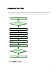
1. Installation Flow Chart...................................................................................................... 7
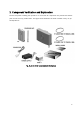
2. Component Verification and Explanation............................................................................. 8
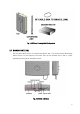
2.1 DONOR UNIT(DU) .................................................................................................... 9
2.2 COVERAGE UNIT(CU) ............................................................................................. 10
3. Preparing for DU and CU Installation ........................
오류! 책갈피가 정의되어 있지 않습니다.
4. BAND SETTING ........................................................... 오류! 책갈피가 정의되어 있지 않습니다.
5. DONOR UNIT(DU) SET Installation ................................................................................... 15
5.1 BRACKET- DU Image .............................................................................................. 15
5.1.1. DU 에 BRACKET – DU Connection Image ........................................................ 15
5.1.2. BRACKET- DU Connection to Installation Place(WALL or POLE) Image................. 15
5.2 BRACKET Connection to DU................................................................................... 16
5.3 BRACKET Connection depending on Installation Place................................................ 17
5.3.1. BRACKET/MTG POLE MOUNTING................................................................... 17
5.3.2. BRACKET/MTG LUMBER WALL Mounting......................................................... 17
5.3.3. BRACKET/MTG CONCRETE WALL Mounting .................................................... 18
5.4 Connection DU(same as 5.1) with BRACKET(same as 5.2) .......................................... 18
5.5 Installation Completion. .......................................................................................... 20
6. CU Wall & Ceil Mount Installation ..................................................................................... 21
6.1. MTG Bracket Image............................................................................................... 21
6.2 GYPSUM BOARD WALL MOUNTING.......................................................................... 22
6.3 CONCRETE WALL MOUNTING ................................................................................. 22
6.4 LUMBER WALL MOUNTING ..................................................................................... 23
6.5 Install Bracket Connection with CU........................................................................... 24
6.6 CU SET Installation Completion................................................................................ 24
7. Power Connection and Optimization SETTING ................
오류! 책갈피가 정의되어 있지 않습니다.
8. Status Check ................................................. ............................................................... 30
8.1 DU FAULT LED ................................................ ...................................................... 30
8.2 CU FAULT LED ...................................................................................................... 30
Appendix A. Product Introduction ........................................................................................ 32
A.1 Overview .............................................................................................................. 32
A.2 Supported Frequency Range ................................................................................... 34
Appendix B. System Specifications...................................................................................... 35
Appendix C. System Block.................................................................................................. 36
Appendix D. Troubleshooting for MPE25K............................................................................. 37