
User Manual


5
<Figures>
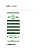
Fig. 1 Installation Flow Chart.................................................................................................................................... 7
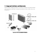
Fig. 2 List of all the Componants in the System ................................... 오류! 책갈피가 정의되어 있지 않습니다.
Fig. 3 Additional CU Componants......................................................... 오류! 책갈피가 정의되어 있지 않습니다.
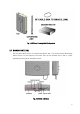
Fig. 4 DONOR UNIT(DU) Image .......................................................... 오류! 책갈피가 정의되어 있지 않습니다.
Fig. 5 CU Image....................................................................................... 오류! 책갈피가 정의되어 있지 않습니다.
Fig. 6 DIP S/W Basic Setting ................................................................. 오류! 책갈피가 정의되어 있지 않습니다.
Fig. 7 MTG Bracket Image....................................................................................................................................... 15
Fig. 8 MTG BRACKET Mounting (Pole, Lumber Wall, Concrete Wall) Connection Image............................. 15
Fig. 9 DU Bracket Connection Diagram ................................................................................................................. 16
Fig. 10 POLE MOUNTING MTG BRACKET-DU Connection Sequence........................................................... 17
Fig. 11 LUMBER WALL MOUNTING MTG BRACKET-DU Connection Sequence........................................ 17
Fig. 12 CONCRETE WALL MOUNTING MTG BRACKET-DU Connection Sequence................................... 18
Fig. 13 DU Unit Wall Mounting ............................................................................................................................... 19
Fig. 14 DU Unit POLE Mounting Installation Completion Diagram...................................................................20
Fig. 15 DU Unit LUMBER WALL Mounting Installation Completion Diagram................................................ 20
Fig. 16 DU Unit CONCRETE WALL Mounting Installation Completion Diagram........................................... 20
Fig. 17 CU MTG Bracket Image & Hole distance.................................................................................................. 21
Fig. 18 CU Bracket Gypsum Wall Mounting.......................................................................................................... 22
Fig. 19 CU Bracket Concrete Wall Mounting......................................................................................................... 23
Fig. 20 CU Bracket Lumber Wall Mounting .......................................................................................................... 23
Fig. 21 CU MTG Bracket – CU SET Connection Image ....................................................................................... 24
Fig. 22 CU Installation Sequence............................................................................................................................. 24
Fig. 23 Power PORT Connection Digram............................................................................................................... 25
Fig. 24 POWER INJECTOR Installation Diagram ............................................................................................... 26
Fig. 25 DU ANT Tilt Diagram .................................................................................................................................. 28
Fig. 26 Verifying reception Status Diagram ........................................................................................................... 29
Fig. 27 DIP S/W Diagram ......................................................................................................................................... 29
Fig. 28 DU LED Diagram ......................................................................................................................................... 30
Fig. 29 CU LED Diagram ......................................................................................................................................... 31
Fig. 30 System Installation Diagram ....................................................................................................................... 32
Fig. 31 Basic Connection Diagram........................................................................................................................... 33