
User's Manual


6
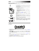
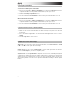
Belt-Pack Transmitter (for Radius 100H headset, Radius 100L lavalier microphone, or
Radius 100M instrument cable)
1. Power/Mute Button: Press this button for 2 seconds to power
the transmitter on or off. Press this button briefly to mute or
unmute the transmitter.
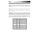
2. Power/Mute LED: This light indicates the power or mute status:
• Red light: The transmitter is on.
• Flashing red light: The transmitter is low on battery power.
• Blue light: The transmitter is muted.
• Flashing blue light: The transmitter is muted and low on
battery power.
3. Sync Button: Press this button to synchronize the transmitter
with the receiver. See Operation to learn more.
4. Display: This display shows the current channel and battery
power level.
5. Battery Compartment (not pictured): Insert 2 AA batteries into
this compartment. Make sure the polarities of the batteries (+ and
–) are correct.
6. Microphone/Instrument Input (mini-XLR): Connect the included
microphone or instrument cable to this input.
7. Gain Selector: Use this switch to set the gain of the audio input
to 10 dB, 0 dB, or -10 dB. For instruments with passive pickups,
we recommend setting this to -10 dB. For instruments with active
pickups, you may want to set this to 0 dB or -10 dB.
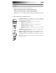
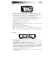
Receiver
Front Panel
1
2
6
3
77
4
5
1. Power Button: Press this button to power the receiver on or off.
2. Display: This display shows the current channel, frequency, and other settings. See Display for
more information.
3. Up/Down (): Press one of these buttons to select the different modes (Manual, Autoscan,
Preset). When searching for channels, press one of these buttons to move to the next-highest or
next-lowest channel, respectively.
4. Sync: Press this button to synchronize the receiver with the transmitter. See Operation to learn
more.
5. Set: Press this button to confirm your mode selection (Manual, Autoscan, Preset) or to set the
current channel. See Operation to learn more.
6. Volume Knob: Turn this knob to adjust the receiver’s output level.
7. Antennae: These antennae receive the signal from the transmitter.
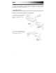
1
6
4
2
3
7
5
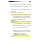
1: Ground
2: Line In
3: Mic In
4: +10V
1: Ground
2: Line In
3: Mic In
4: +10V
Mic Level
Line Level
3 4 1
2