
User's Manual


INNCOM B574 Datasheet Page | 4
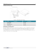
MechanicalDrawings
Figure 4: Mechanical Drawings
Item Description PartNumber
1 Top Housing 53-8084
2 Radio Module 02-9994
3 Main PCBA 02-9845
4 Bottom Housing 53-9918
5 Din Rail Tab 53-9919
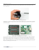
MountingConsiderations
The B574 Network Controllers are designed for mounting in a variety of applications. The bottom
housing is equipped with a channel and tab for DIN rail mounting and therefore does not require
any additional screws or hardware for installation. For screw-mounted applications, there are 4
countersunk holes located in the bottom housing that can be accessed by removing the top cover
and Printed Circuit Board Assembly (PCBA).