
User's Manual


INNCOM B574 Datasheet Page | 6
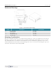
the cable, cable channels and connections are always aligned in the correct orientation in a daisy-
chained application.
Figure 7 B574 Top Housing Removal
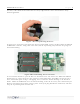
To gain access to headers and connectors located on the PCBA, remove the B574 from the DIN rail
or NEMA box enclosure. Using a flat screw driver, lift the top housing away from the snap tangs on
the bottom housing.
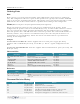
Figure 8 B574 Mounting Screw Locations
To screw mount the B574, open the B574 as described above and remove the PCBA. The PCBA is
held in place by 4 tangs located at the perimeter of the PCBA. Once the PCBA is removed, locate
the 4 countersink posts. Using a self-tapping screw, mount the bottom housing to the intended
fixture. Mount the PCBA back on to the bottom housing, make the necessary wire connections (see
Headers and Connectors below), connect power to DC jack, plug in Ethernet connection, and then
snap the top housing back onto the unit.