
User Manual

E V O R A D a t a s h e e t P a g e 2 o f 1 0
standard dimension mounting bracket, for instance, allowing EVORAs to be ganged with other products (similar to
the S-Series). EVORA products come factory assembled.
Categories of Load Assembly Load Switching
• TRIAC dimmer provides dimming control of resistive light loads such as incandescent, halogen, and
TRIAC dimmable LEDs. The TRIAC dimmer can dim 100–120VAC loads up to 500W.
• FET dimmer dims capacitive loads such as dimmable fluorescent lamps and electronic ballasts. It can also
dim resistive loads such as incandescent, halogen, and dimmable LEDs. The FET dimmer is designed to
dim 100–120VAC up to 350W.
• Relay power supply switches capacitive, inductive, resistive, and general purpose loads up to 500W.
• Master contactor controls 30A relay at 120–240VAC.
• 200mA power supply used for applications where EVORA must be line powered but does not require
load dimming or switching.
• Low-voltage adapter allows the EVORA products to run in a +12VDC powered device that does not
actuate a load. This is very similar to the legacy S5XX product.
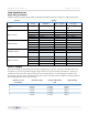
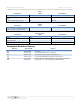
Load Assembly Parallel Power Supplies
The WBI actuators operate in parallel to supply a higher load capacity on the +12VDC rail than that achievable by a
single actuator. The total output power of the actuators in parallel is based on the voltage specifications at maximum
load versus the output current at maximum load and nominal recovery time after a foldback condition occurs. This
design can aggregate up to 6 actuators into a system that permits up to a combined 990mA (~1A) +12VDC output.
See Class 2 Output table below.
Additional Load Assembly Technical Features
• Air-gap relay required (for dimmers meeting UL 508). Where solid state dimmers are used, disengages
the load from the line power in the event that a failed actuator causes a short or a closed circuit (as with a
FET dimmer), a possible electric shock risk during routine maintenance or lamp replacement.
• Additional overload detection circuit for FET dimmer that senses a catastrophic overload / short and
shuts down the dimmer to protect the solid state circuitry.
• Dimming linearization curve may be set by application engineer to calibrate the duty cycle of a Pulse
Width Modulated signal driving the various lamp types that could be used.
• Self contained actuator that can be used without the user interface. This is useful during installation (with
EVORA) and in repair to isolate symptoms related specifically to the actuator.
Load Assembly Installation
Locate the fuse panel and remove fuses or ensure the breaker is in the OFF position before installing the Load
Assembly.
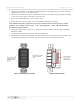
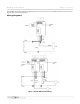
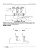
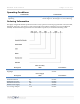
1. Pull the class-2 wires for Ground (Brown), +12VDC (Red) and S5bus (Orange) and digital inputs into the
wall box (See Wiring Diagrams). Make the connections using a dolphin DC-1000P Super B connector or
equivalent type connector to the S5bus or digital input harnesses and connect them to the appropriate
header on the Load Assembly.
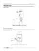
2. Prepare the line voltage wiring by stripping back the insulation 16mm (5/8th inch).
3. Connect the Green (Earth) Cable attached to the Load Assembly Strap to Earth.