
User Manual


E 5 2 8 P r o d u c t G u i d e P a g e 6 o f 1 8
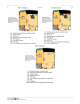
Headers
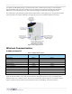
The headers for the e528.2G, 3G and 4G
*
thermostats are substantially the same, though the layouts and labeling on
the PCB are slightly different (see Figure 5 above). The statements and tables below detail only the headers that differ
in function.
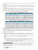
Low Voltage comm / device connector: This header accepts the provided 6-pin harness used to connect low
voltage communication, door/window position switch, and other room devices to the e528. Table 3 shows the
pinout for the 2G low voltage comm / device connector and lists typical functions for each pin. Table 3a shows
pinout and function for the 3G and 4G. For specifics, refer to the as-built wiring diagrams.
Table 3. e528 2G Low Voltage Harness (P/N 62-1462) Pinout
Wire Color Female
Connector
Male
Connector
Function Comment
Brown 1 1 Common GND
Red 2 2 12VDC Out/In 12VDC Supply
Orange 3 3 S5 Bus Data Tx/Rx or IN 2 Communication Bus
Yellow 4 4 IN 1 Door, Window, PIR, Other
Green 5 5 CINET B RS485 Twisted Pair
Blue 6 6 CINET A RS485 Twisted Pair
Table 3a. e528 3G/4G Low Voltage Harness (P/N 62-1467) Pinout
Wire Color Female
Connector
Male
Connector
Function Comment
Brown 1 1 Common GND
Red 2 2 12VDC Out/In 12VDC Supply
Orange 3 3 S5 Bus Data Communication Bus
Yellow 4 4 Digital Input Door, Window, PIR, Other
Green 5 5 No Connection
Blue 6 6 No Connection
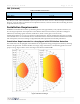
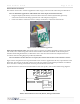
External temperature control sensor: This header accepts the wiring harness from an external temperature probe
that can be used to supply the e528 with remote temperature measurements. The e528 uses a 10K 1% thermistor
for external temperature measurement. This external temperature sensor can be used to monitor room
temperature at a different location from where the e528 is mounted or to monitor pipe water temperature.
RS485 Networks: (refer to Figure 5)
E528.2G can be connected to the RS485 FLN5 network by installing the 02-9496 module, then connecting the
RS485 network to pins 5 and 6 of the low voltage comm /device connector as described in Table 3 above.
E528.3G cannot act as the media gateway for in-room traffic towards the RS485 network. The most common
way to connect the e528.3G is to connect a PC-485.S5 (P/N: 01-9905) on the S5bus.
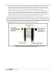
E528.4G
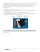
E528.4G to 2G RS485 Networked Application: with or without door switch input (See Figure 6 below)
• Using the adapter (P/N 203-251), connect the harness from the wall box (P/N 62-1462) previously
connected to the thermostat being replaced to H1 of the adapter.
• Connect the harness H3 (rainbow) of 203-251 to the low voltage comm/device connection of the e528.4G
*
“2G,” “3G,” and “4G” are internal INNCOM product designations used for convenience to differentiate
individual hardware configurations. No difference in device capability or effectiveness is implied. Due to end-of-
life for certain 2G and 3G components, the e528.4G is now the standard INNCOM install, but 2G and 3G
installations are still supported.