
User Manual


E 5 2 8 P r o d u c t G u i d e P a g e 7 o f 1 8
• Connect the harness H2 (black) of 203-251 to the RS485 header of the e528.4G
NOTE: Take care to not reverse the connections to the e528.4G!
E528.4G New Installation
Stand alone application with/without door switch input
• Using the harness (P/N 62-1467), make the appropriate wire connections, then plug the harness into the
low voltage comm/device connection of the e528.4G
RS485 Networked Application with/without door switch input (See Figure 7)
• Using the harness (P/N 62-1467), make the appropriate wire connections, then plug the harness into the
low voltage comm/device connection of the e528.4G.
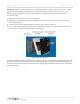
• Using the adapter (P/N 203-250) and P/N 62-1532-B.12 cables, connect the RS485 A pair to the two pin
RS485 In header and the RS485 B pair going to the next thermostat to RS485 Out header on the 203-250.
• Connect the harness of 203-250 to the RS485 network header of the e528.4G.
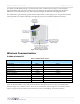
Figure
7
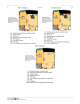
E528.4G New RS485 Networked Application
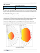
Figure
6
4G to 2G RS485 Networked Application