
User Manual


E 5 2 8 P r o d u c t G u i d e P a g e 8 o f 1 8
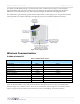
E528.4G Retrofit Installation
The e528.4G can be used to retrofit an application where a legacy e528 was used. Follow the procedure below:
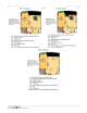
4G to 2G Standalone application: with/without door switch input (no backhaul network)
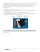
• Using the adapter (P/N 203-013) connect the harness from the wall box (P/N 62-1462) previously
connected to the thermostat being replaced to H1 of the adapter (see Figure 8).
• Connect the harness of 203-013 to the low voltage comm/device connection of the e528.4G.
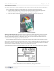
Molex 10-position female socket: This female socket accepts the provided 10-pin Molex connector pre-wired
with 8-inch, color-coded wiring leads. These leads should be connected to the 24VAC or 100–277VAC power,
valve/fan control wiring from the FCU, or other HVAC device with wire nuts inside in the wall junction box in
accordance with the wiring diagram provided by INNCOM.
Note: For installations in which all leads are not required, the extraneous leads should be cut off at the Molex connector.
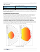
Figure 8 shows the pinout for the 10-position Molex male connector supplied with all relay output models of the
thermostat. The end view of the male connector from the wire insertion side with the pin numbers is indicated.
This is the same as looking at the female connector point on the back of the e528.
Typical functions for each wire are listed in Tables 4 and 5. For specifics, refer to the as-built wiring diagrams.
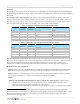
Table 4. 24VAC Harness Color Code, Pinout, and Typical Functions
Figure 8 e528.4G to 2G Standalone application
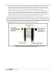
Figure
9
10
-
Pin Molex Connector (Part No. 62.1455 or 62.1464.R)