View 3 ARC Fusion Splicer User Manual Please read this manual before operating your fusion splicer, and keep it for future reference. 2014/10 Rev.0.
View 3 User Manual 1
2
Contents 7 Introduction 8 Chapter 1: Technical specifications 8 Applicable fiber type 8 Splice loss 8 Splice mode 8 Heat oven 9 Power supply 9 Dimensions and weight 9 Environment 9 Other 10 Battery precautions 11 Chapter 2: Installation 11 Safety warnings and precautions 11 Operational safety warnings 12 Maintenance and external care precautions 13 Transport and storage precautions 14 Installation 14 Unpacking the splicer 16 Splicer overview 17 Power supply 17 Batte
20 Touch screen On/Off 21 Fiber zoom function on screen 21 Preparing the fibers 22 How to make a splice 22 Placing the fibers 22 Inspecting the fibers 23 Splicing 24 How to protect the splice 24 Heating procedure 25 Chapter 4: Splice Programs 25 Displaying the active splice program 26 Selecting a splice program 27 General splicing steps 27 Pre-fusion 27 Fusion 27 Splicing process 28 Splice program parameters under general splicing process 30 Chapter 5: Splice Option 30 S
36 Operation procedure 37 Dust check 37 Operation procedure 37 Motor calibration 38 Operation procedure 38 Arc calibration 38 Operation procedure 39 Electrode setting 39 Update software 40 Chapter 8: Other Functions & Utilities 40 Data storage 40 Display splice record 40 Delete splice record 40 Cancel data storage 41 System setting 42 Monitor position 43 Power save option 43 System information 44 Appendix I: Reasons for high splice loss and solutions 46 Appendix II: Li
Important: INNO Instrument strongly recommends all users to read this manual before operating VIEW 3.
Introduction Thank you for choosing VIEW 3 Arc Fusion Splicer from INNO Instrument. View 3 adopts innovative product design and exquisite manufacturing technology so as to deliver unprecedented splicing experience to customers.The totally new technology greatly reduces splicing and heating time, and advanced estimation method and alignment technique ensure the accuracy of splice loss estimation.
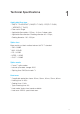
Technical Specifications 1 Applicable fiber type • SM(ITU-T G.652&G.657) / MM(ITU-T G.651) / DS(ITU-T G.653) • Fiber count: Single • Applicable fiber cables: 0.25mm - 3.0mm / Indoor cable • Applicable fiber diameter: Cladding diameter: 80~150μm, / NZDS3(ITU-T G.655) Coating diameter: 100~1000μm Splice loss Measured by cut-back method relevant to ITU-T standard: • SM : 0.03dB • MM : 0.02dB • DS : 0.05dB • NZDS : 0.05dB • G.657 : 0.
Power supply • Standard AC power voltage: AC 100-240V, 50-60Hz • Standard DC power voltage: DC 9-14V Dimensions and weight • Size: Height x Width x Depth = 152mm x 147mm x 175mm • Weight: 2.31kg (battery included) Environment • Operating condition: 0~5000m above sea level, 0~95% relative humidity, • Storage condition: 0~95% relative humidity, -40~80℃ • Battery: -20~30℃ for long time storage -10~50℃, 15m/s max wind speed Other • Viewing and displaying method: two cameras and 5.
Battery precautions • DO NOT collide the battery with sharp or hard objects. • DO NOT transport or store the battery with metals simultaneously. • DO NOT throw, drop, impact or bend the battery. • DO NOT strike the battery with hammers or tread on it. • DO NOT connect the anode and cathode of the battery to metals such as • DO NOT let the anode and cathode contact with the external aluminum coating • DO NOT disassemble the battery under any circumstances.
Installation 2 Safety warnings and precautions As VIEW 3 is designed for fusion splicing silica glass optical fibers, it is very important that the splicer should not be used for any other purposes. The splicer is a precision instrument and must be handled with caution. Therefore, you must read the following safety rules and general precautions in this manual regarding the use and handling of VIEW 3 at any time.
• Users should always wear safety glasses during fiber preparation and splicing operation. Fiber fragments can be extremely dangerous if they are ingested or come into contact with eyes, skin. • Take out the battery immediately if the followings are observed when using the splicer: • Fumes, bad smell, abnormal noise or over heat. • Liquid or other matter falls into cabinet • The splicer is damaged or dropped. Note: If any of these faults occurs, please contact our service center immediately.
Transport and storage precautions • When the splicer is moved from cold to warm environment, you should allow the splicer to warm up gradually. Otherwise, the condensation generated inside will bring harmful effects to the splicer. • Pack the fusion splicer well for long time storage. • Keep the splicer clean and dry. • The splicer is precision adjusted and aligned. Always keep the splicer in its carrying case to protect from damage and dirt.
Installation Important: Please follow the instructions below carefully. Unpacking the splicer Hold the handle upwards, then lift the splicer out of the carrying case.
Documents (not shown) • User manual • Supplier’s declaration of conformity • Test protocol Equipped with VFH-40 fiber holder (Standard package) Chapter 2 Installation 15
Splicer overview Loop Heat oven On / Off button Control buttons Power supply / Battery Display USB 2.
Power supply Battery Switch off the splicer. Press the [Release] button at the side of the splicer and take out the battery from the splicer. Insert Release button Take out the battery Insert the battery into the power unit dock until it clicks into place. Charge the battery Connect the battery charger to the battery. Step 1 Step 2 Charging progress is indicated by five lit LEDs continuously sweeping from 20% to 100% on the battery indicator (see below).
Note: Check and make sure the remaining battery capacity is 20% or greater before splicing. If the battery capacity is less than 20%, please use AC / DC adapter to power the splicer. Heat will be generated during the charging process. Do not stack the battery on top of AC / DC adapter while charging. How to check remaining battery capacity You have two ways to check remaining battery capacity.
Basic Operation 3 Turning on the splicer Press [Power] key on the operation panel, and wait the splicer to be turned on and move to Workbench page. Adjusting the monitor position Users can adjust the monitor position by moving it with a desired angle in purpose of operation convenience.
Adjusting the monitor brightness In the initial interface, press “◀” or “▶” to adjust the monitor brightness until a clear image can be seen. Note: The LCD monitor is a precise component produced by manufacturing factory under strict quality control. However, some tiny dots in different colors may still remain on the screen. Meanwhile, the screen brightness may not appear uniform, depending on its viewing angles. Note that these symptoms are not defects, but are natural phenomenon.
Fiber zoom function on screen Users can zoom in the fiber image by double tapping on the screen so as to observe the splicing result and check the splicing condition. Preparing the fibers 3 Steps should be carried out before splicing: Step 1: Strip the fiber Remove at least 50mm of secondary coating (valid for both tight and loose tube secondary coating) and approximately 30~40mm of primary coating with an appropriate stripper.
Important: Make sure that the bare fiber and its cleaved section are clean. • Avoid putting the fibers on a dusty working surface. • Avoid swaying the fibers in the air. • Check if the V-grooves are clean. If not, must clean it with pure alcohol-soaked • Check if the fiber holders are clean. If not, must clean it with pure alcohol-soaked cotton swabs. cotton swabs. How to make a splice Placing the fibers • Open the windproof cover. • Raise the fiber holders.
Dust on fiber Tag Chip Large cleave angle Note: The fibers are checked automatically when you press “Set” button. The splicer automatically focuses the fibers and checks for damage or dust particles. Splicing • Select any appropriate splice mode. • Start splicing by pressing [SET] button. Note: If the splicer is set as “Auto mode”, splicing will start automatically once the windproof cover is closed. How to protect the splice After splicing, put the fiber with heat-shrink sleeve into the heat oven.
Open the heat oven lid Move into the heat oven clamp Splicing position Heating LED indicator [HEAT] button Chapter 3 Basic Operation 24
4 Splice Programs VIEW 3 has an intuitive and simple but very powerful program structure to operate. Splice programs define arc currents, splice times as well as various parameters used when performing a splice. Therefore, it is essential to select the correct splice program. There are a number of “preset” splice programs for common fiber combinations. Therefore, it is much easier to modify and further optimize the parameters for more unusual fiber combinations.
Selecting a splice program Select [Splice mode] from the main menu. Select [Splice mode] and select [Select splice mode]. Select an appropriate splice mode Selected splice mode appears on the screen. Press [RESET] button to return to initial interface page.
General splicing steps This section explains the steps involved in automatic splicing process and describes how various program parameters are related to this process. The normal splicing process can be divided into two sections; pre-fusion and fusion. Pre-fusion During pre-fusion, the splicer performs automatic alignment and focusing, where the fibers are subjected to a low pre-fuse current for cleaning purposes; a pre-fuse image is also taken.
Splice program parameters under general splicing process Parameter Description A list of splice modes stored in the splicer database. Upon inputting the Template appropriate mode, the selected splice mode stored in database area is copied to a user-programmable area. Name Note Arc Adjust Pull Test Title for a splice mode expressed in up to seven characters. Detailed explanation for a splice mode expressed in up to 15 characters. It is displayed at [Select splice mode] menu.
A cleaning arc burns out micro dust on the surface of the fiber with an arc Clean Arc Time discharge for a short period of time. The duration of the cleaning arc can be changed by this parameter. Set the prefuse arc power from the beginning of arc discharging to the beginning of fibers propelling. If [Preheat Arc Value] is set too low, axial Preheat Arc Value offset may occur if cleaved angles are relatively poor.
5 Splice Option Setting up splice mode • Select [Splice option] in menu. • Select a parameter to be changed. Parameter Description If “Auto Start” is set to “On”, splicing starts automatically as soon as the Auto Start windproof cover is closed. Fibers should be prepared and placed into the splicer in advance. If “Pause1” is set to “On”, splicing operation pauses when fibers are Pause 1 forwarded to gap-set position. Cleave angles are displayed during the pause.
Loss Setting to “OFF” ignores the faults and continues to complete the splicing Fat even if the message “Loss Error”, “Cleave Shape Error”, “Fat Error”, or “Thin Thin Error” appears. Fiber Image On Screen Gap Set Pause1 Align Pause2 Set the displaying method of the fiber image on the screen during splicing operation.
Heater Mode 6 The splicer provides 32 heat modes including 3 heat modes preset by INNO Instrument and the rest that can be defined by users. Select a heating mode that best matches with the protection sleeve used. For each type of protection sleeve, VIEW 3 has its optimum heating mode. These modes can be found in the database area for reference. Copy the appropriate mode and paste it to the user–programmable area. Users can edit those parameters.
Select heat mode. Selected heat mode appears on the screen. Press [RESET] button to return to initial interface. Editing heat mode Heating conditions stored in heater mode can be edited or changed. Select [Edit Heat Mode] in [Heater mode] menu. Select the mode to be edited.
Select the parameters to be edited. Deleting heat mode • Select [Heater Mode] menu. • Select [Delete Heat Mode]. • Select the heat mode to be deleted. Note: The gray modes (40mm, 60mm) are the system preset initial heat modes which cannot be deleted. Heat mode parameters Parameter Template Name Note Heater Control Heat Temperature Description Set sleeve type. List of all heat modes are displayed. Selected mode will be copied to a user-programmable area. Title for a heat mode.
Maintenance Menu 7 The splicer has a function to perform routine maintenance. This chapter describes how to use the maintenance menu. • Press □ button, and select [Maintenance menu]. • Select a function to perform. Replace electrodes As electrodes are worn out during the splicing process, oxide generated on the tips of electrodes should be regularly eliminated. It is recommended that the electrodes should be replaced after 3500 arc discharges.
• INNO Instrument strongly recommends all users to do stabilizing electrodes and arc calibration after electrodes replacing to keep good splice results and splice strength (Details are described below). Stabilize electrodes In the event of sudden change in environmental conditions, especially when the splicer is moved from lower altitudes to higher altitudes, the arc power may become unstable, resulting in higher splice loss. In such case, it takes time for arc power to be stabilized.
• Execute [Diagnostic test], then the following checks will be made. Parameter 1 LED Calibration 2 Dust Check Description Measure and adjust the brightness of LED. Check the optical path for dust or dirt and judges whether they disturb fiber observation. If contamination exists, press the return button twice to display the location. 3 Motor Calibration 4 Arc Calibration Automatically calibrate the speed of 4 motors. Automatically calibrate the arc power factor and fiber splicing position.
Operation procedure • Select [Motor Calibration] in [Maintenance Menu]. • Load prepared fibers in the splicer, and press [SET]. • Speeds for all motors are automatically calibrated. Upon completion, the message “Operation Complete” will be displayed. Note: Perform this function when “Fat” or “Thin” error occurs, or fiber aligning or focusing takes too much time.
• The splicer will show up two values on the screen after each arc calibration. If the value shown on the right-hand side meets 11±2, the message “Operation Complete” will be shown on screen. Otherwise, set prepared fibers on the splicer again and redo arc calibration until the message “Operation Complete” is displayed. Electrode setting Set the electrode change warnings. INNO Instrument recommends replacing the electrodes every 3500 discharge to ensure the best splice results.
Other Functions & Utilities 8 Data storage This splicer stores up to 2000 splicing results. Contents of data stored are different depending on the splicing mode. Display splice record Splicing results stored in the splicer can be displayed. • Select [Display Splice Record] in [Data Storage] menu. Delete splice record Splicing results can be cleared by part or whole.
System setting Parameter Buzzer Temperature Unit Automatic Heating Description Set On/Off of the buzzer. Set the unit of temperature. If “Automatic heating” is set to “ON”, heat oven will perform heating automatically when the fiber is put into the heat oven. Language Monitor Position Select a language to be displayed on the screen. Set the operational direction of splicer. [Front] is for monitor forward operation. [Rear] is for monitor backward operation. Refer to next page for details.
Monitor Position The direction of the splicer display before shipping from the factory is set to “Front”, but users can change it to “Rear”. When [Monitor position] is changed, the direction of the arrow keys is reversed. Changing monitor position • Select [Monitor Position] in [System Setting] menu. • Select the desired monitor position (front/rear). Note: Press ▲ or ▼ buttons to swift the monitor position quickly on Workbench.
Power save option This function is important for power conservation. If the power saving function is not set during battery use, the number of splice cycles will be reduced. • Insert a power unit, and turn on the splicer. • Select [Power Save Option] in [System Setting] menu. • Change values of [Monitor Shut Down] and [Splicer Shut Down].
Appendix I Reasons for high splice loss and solutions Symptom Name Core Axial Offset Core Angle Error Reason Solution Dust on V-groove or fiber Clean V-groove and fiber holder. holder. Dust on V-groove or fiber Clean V-groove and fiber holder. holder. Bad fiber end-face quality. Check if fiber cleaver is well-conditioned. Bad fiber end-face quality. Core Curve MFD Mismatch Check if fiber cleaver is well-conditioned.
Arc power is not adequate. Thin Some arc parameters are not adequate. Line Some arc parameters are not adequate. Perform [Arc Calibration]. Adjust [Preheat Arc Value], [Preheat Arc Time], or increase [Overlap]. Adjust [Preheat Arc Value], [Preheat Arc Time], or [Overlap]. Note: A vertical line sometimes appears at the splice point when MM fibers or dissimilar fibers (different diameters) are spliced. We call it as “Splicing line”.
Appendix II List of error messages During the splice operating process, if the error messages are shown on the screen, please follow the solution precisely as shown in the list below. If it is not possible to solve the problem, the splicer may require service by a qualified service center. In this case, please contact sales agents. Error Message Left Fiber Place Error Reason Solution The fiber endface is placed Press RESET button, and reload beyond the electrode centerline.
Dust on the fiber surface. Re-prepare the fiber. Different fiber types on two sides. AUTO mode is not applicable in this case; select a suitable splice Unknown Fiber Type mode to redo splicing. The fiber is a non-standard fiber. AUTO mode can only detect standard SM, MM, NZ fibers. Fiber Clad Over Limit Fiber Endface Gap Wrong Fiber edge is not located in the Adjust the fiber position; perform camera range. [Motor Calibration]. [Overlap] is too much. Adjust [Overlap] parameter.
Dust or dirt on the fiber surface. The lenses are covered with dust. Fiber is Dirty Fat Splicing Point Thin Splicing Point Appendix II Prepare the fiber again. Perform [Dust check] after cleaning the lenses. [Clean Arc Time] is too short. Set [Clean Arc Time] to 180ms. It is difficult to identify the fiber Use MM splice mode (clad align- core by using the method of core ment) to splice the unidentified alignment to splice. fiber core. [Overlap] is too much. Adjust [Overlap] parameter.
Appendix III Frequent questions and troubleshooting Note: The solutions of common faults for reference are as follows. Please contact sales agents for further support if needed. • Power does not turn off when pressing ON/OFF button. • Press and hold the key until the LED blinks, and then release the button to turn off the splicer. • Few splices can be made with a fully charged battery pack. • • Enable the power save option.
• AUTO mode is only applicable for SM, MM, NZ fibers. AUTO mode may not be able to identify while splicing special fibers. • Mismatch between estimated splice loss and actual splice loss. • The estimated loss is just an estimated number by calculation, for reference only. • • • • The optical components of the splicer need to be cleaned. Fiber protection sleeve does not shrink completely. Extend the heating time. Method to cancel heating process.
Over 70 countries Europe Branch Office Exclusive distributors & dealers 97companies Korea Head Office China Branch Office USA Branch Office www.innoinstrument.com Copyright ⓒ 2014 INNO Instrument Inc. All rights reserved.