User Manual New friendly GUI design SOC Support Screen Zoom Remote Control VIEW 3 Pro MONITORING WEB SERVICE CLAD-ALIGNMENT FUSION SPLICER Please read this manual before operating your fusion splicer, and keep it for future reference. Ver V1.
Content Preface Chapter 1 Technical Parameters VIEW 5 Pro 4 5 1.1 Applicable Fiber Type.......................................................................................................................................... 5 1.2 Splice Loss............................................................................................................................................................ 5 1.3 Splice Mode........................................................................................
7.2 Replace Electrodes................................................................................................................................. 21 7.3 Stabilize Electrodes................................................................................................................................ 22 7.4 Motor Calibration................................................................................................................................... 22 7.5 Dust Check............................
Preface VIEW 5 Pro Thank you for choosing VIEW 3 Pro Arc Fusion Splicer from INNO Instrument. VIEW 3 Pro adopts innovative product design and exquisite manufacturing technology so as to deliver unprecedented splicing experience to customers. The totally new technology greatly reduces splicing and heating time, and advanced estimation method and alignment technique ensure the accuracy of splice loss estimation.
Chapter1 - Technical Parameters 1.1 Applicable Fiber Type * SM(ITU-T G.652&T G.657)/MM(ITU-T G.651)/DS(ITU- T G.653)/NZDS (ITU-T G.655) * Fiber count: Single * Applicable fiber / cable diameter: 0.2mm to 3.0mm/Indoor Cable * Applicable fiber diameter: Cladding diameter: 100 to 125μm 1.2 Splice Loss Same fiber is spliced, measured by cut-back method relevant to ITU-T standard. The typical values of splice loss are: * SM:0.03dB * MM:0.01dB * DS:0.05dB * NZDS:0.05dB * G.657:0.03dB 1.
1.8 Other VIEW 5 Pro * Observation and display: Two cameras, 5-inch color LCD display, Full touch screen. * 320x magnification for single X or Y view, or 520x magnification for double click X or Y view. * Pull test:1.96 to 2.25N. * Terminals: Type C / SIM. 1.9 Battery precautions 1) Do not touch or hit battery with pointed or sharp items. 2) Do not transport or store the battery together with metals. 3) Do not throw, drop, impact, or bend battery, or any knock or stomp on the battery is forbidden.
Chapter 2 - Installation 2.1 Safety Warning and Precautions As VIEW 3 Pro is designed for fusion splicing silica glass optical fibers, it is very important that the splicer should not be used for any other purposes. The splicer is a precision instrument and must be handled with caution. Therefore, you must read the following safety rules and general precautions in this manual regarding the use and handling of VIEW 3 Pro at any time.
Transport and Storage Precautions VIEW 5 Pro ① When the splicer is moved from cold to warm environment, you should allow the splicer to warm up gradually. Otherwise, the condensation generated inside will bring harmful effects to the splicer. ② Pack the fusion splicer well for long time storage. ③ Keep the splicer clean and dry. ④ The splicer is precision adjusted and aligned. Always keep the splicer in its carrying case to protect from damage and dirt.
2.
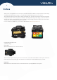
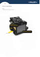
VIEW 5 Pro 2.4 Power Supply Method Battery Following is the way of installing a battery. Shut off fusion splicer. Press on release button at lateral,drawing the battery out of the fusion splicer. Place the battery into power unit slot until you push it into the right place.
Chapter 3 - Basic Operation 3.1 Turn On the Splicer Press button on the operation panel, and wait the splicer to be turned on and move to Workbench page. ⚠ Note: The LCD monitor is a precise component produced by manufacturing factory under strict quality control. However, some tiny dots in different colors may still remain on the screen. Meanwhile, the screen brightness may not appear uniform, depending on its viewing angles. Note that these symptoms are not defects, but are natural phenomenon. 3.
VIEW 5 Pro 3.3 How to Make a Splice Put the optical fiber in ① Open the safety shield. ② Raise the fiber clamps. ③ Position the fibers into V-grooves. Make sure the fiber ends are between the V-groove edges and the electrode tip. ④ Clamp the fiber in position by lowering both sets of fiber clamps. ⑤ Close the safety shield. ⚠ Note: Make sure to avoid sliding the fibers along V-grooves, but rather position them over V-grooves and tilt them down into place (as shown below).
3.4 How to Protect the Splice After splicing, put the fiber with heat-shrink sleeve into the heat oven. Press [Heat] button to execute heat-shrink process to strengthen the splice point. Heating Procedure ① Open the heat oven lid ② Lift the left and right fiber holders on the splicer. Hold the heat-shrink sleeve (previously placed onto the fiber). Lift the spliced fibers and hold them taut. Then move the heat-shrink sleeve to the splice point.
VIEW 5 Pro Open the heat oven lid Splicing position move into heat oven clamp Heating LED indicator [HEAT] Button
Chapter 4 - Splice Mode VIEW 3 Pro has an intuitive and simple but very powerful program structure to operate. Splice programs define arc currents, splice times as well as various parameters used when performing a splice. Therefore, it is essential to select the correct splice program. There are a number of “Preset” splice programs for common fiber combinations. Therefore, it is much easier to modify and further optimize the parameters for more unusual fiber combinations. 4.
VIEW 5 Pro 4.3 General Splicing Steps This section explains the steps involved in automatic splicing process and describes how various program parameters are related to this process. The normal splicing process can be divided into two sections: pre-fusion and fusion. Pre-Fusion During pre-fusion, the splicer performs automatic alignment and focusing, where the fibers are subjected to a low prefusion current for cleaning purposes; a pre-fusion image is also taken.
4.4 Parameters for Normal Splicing Process Parameter Template Name Note Align Type Arc adjust Pull test Loss estimate Minimum loss Loss Limit Core angle limit Cleave angle limit Gap position Gap Overlape Cleaning Arc time Preheat Arc value Preheat Arc time Fuse Arc value Fuse Arc time Description A list of splice modes stored in the splicer database is displayed.
VIEW 5 Pro Chapter 5 - Splice Option 5.1 Splice Mode Setting 1 Select [Splice option] in menu. 2 Select a parameter to be changed. Parameter Auto start Pause 1 Pause 2 Cleave angle Core angle Loss Fat Thin Pause 1 Align Pause 2 Arc Estimate Gap set Description If“Auto start”is set to ON, splicing starts automatically as soon as the wind protector is closed. Fibers should be prepared and placed into the splicer in advance.
Chapter 6 - Heater Mode The splicer provides max 32 heat modes including 7 heat modes preset by INNO Instrument and the reset that can be defined by users. Select a heating mode that best matches with the protection sleeve used. For each type of protection sleeve, VIEW 3 Pro has its optimum heating mode. These modes can be found in the database area for reference. Copy the appropriate mode and paste it to the user–programmable area. Users can edit those parameters. 6.
VIEW 5 Pro ② Select the parameters to be edited. 6.3 Delete Heat Mode ① Select [Heater Mode] menu. ② Select [Delete Heat Mode]. ③ Select the heat mode to be deleted ⚠ Note: The gray modes (20mm, 30mm) are the system preset initial heat modes which cannot be deleted Heat Mode Parameters Parameter Description Template Set sleeve type. List of all heat modes are displayed. Selected mode will be copied to a user-programmable area.
Chapter 7 - Maintenance Menu The splicer has a function to perform routine maintenance. This section describes how to use the maintenance menu. ① Select [Maintenance Menu]. ② Select a function to perform. 7.1 Maintenance VIEW 3 Pro has a built-in diagnostic test function that allows the user to evaluate several critical variable parameters with only one simple step. Perform this function in case of splicer operation fault.
VIEW 5 Pro ④ Clean the new electrodes with alcohol-impregnated clean gauze or lint-free tissue, and install them in the splicer. I) Insert the electrodes in the electrode covers. II) Place the electrode covers on the splicer, and tighten the screws. ⚠ Note: Do not pull out wiring when replacing electrode. Do not exceed the normal finger strength when tightening screw.
7.5 Dust Check Through image acquisition, the splicer detects dust and contaminants on the splicer, camera, and objective lenses that may result in improper splicing. This function checks the optical path for the presence or absence of contaminants, and judges whether they will affect the quality of fiber splicing. Operation Procedure ① Select [Dust check] in [Maintenance menu]. ② If fibers are set in the splicer, remove them and press [Set] again to start the dust check.
Chapter 8 - Other Functions & Utilities VIEW 5 Pro 8.1 Data Storage This splicer stores up to 10,000 splicing results. Contents of data stored are different depending on splicing mode. Display Splice Record Splicing results stored in the memory can be displayed with image. Enter [Splice Mode] - > [Data Storage] Menu and Select [Display Splice Record] to view. Edit Splice Record Available to enter Splice location information. It is saved with splice data.
8.3 Time Lock 8.3.1 Time Lock setting ① Enter [main menu] - [System Setting] - [System Setting] - [Time Lock] ② Enter device password ③ Available to set up to 6 dates [YY/MM/DD] for Time Lock ④ Press “R” button to reset the date ⑤ Press “o” button to save after setting ⑥ Check save notification on bottom of screen, “Data save done!” ⑦ Device is locked on set dates, enter device password to unlock 8.3.
VIEW 5 Pro Power Save Option This function is important for power conservation. If the power saving function is not set during battery pack use, the number of splice cycles will decrease. (1) Insert a power unit and turn on the splicer. (2) Select [Power Save Option] in [System Setting] menu.
Chapter 9 - VIEW PRO MANAGER 9.1 Preparation * Load battery and turn on the device. * Detach the SIM card Tray from under the USB cover of the splicer * Insert Nano SIM card to slot on the right side of machine. Mini-SIM (Standard-size) Micro-SIM Nano-SIM *Only Nano-SIM Card Support 9.
* Networks status can be observed on workbench interface * Check Network and GPS activation icon on workbench (GPS signal is activated at open area) ICON Description GPS is activated GPS is not activated Network is activated Attempt to activate Network No SIM Card * In case of Network fail, please refer to below. - SIM card should be unlocked.
9.
VIEW 5 Pro 9.6 Feature of VIEW PRO MANAGER 9.6.1 Monitor 2 4 5 3 1 1)Device list with status icons (electrode warning, battery, SW version). * Default grouping cannot be deleted. 2) Add/Remove group, group management. 3)Splice data of selected devices (User, Model, Estimated loss, Location, etc). 4)Select the period to search splice data 5)Current device location with device information (location, name, model, etc). 9.6.
More Introduction and guidance can be found in “HELP” under account menu.
VIEW 5 Pro Appendix I High Splice loss: Cause and remedy Symptom Name Fiber core axial offset Fiber core angle error Fiber core bending The mode field diameters mismatch Dust combustion Bubbles Separation Fat Thin Splicing line Cause There’s dust in V-grooves and fiber hammer Remedy Clean the V-grooves and fiber hammer There’s dust in V-grooves and fiber hammer Clean the V-grooves and fiber hammer Bad fiber end-face quality Check the cleaver Bad fiber end-face quality Pre-fuse power too low
Appendix II Error Message List An error message may appear on the screen when using a splicer, the solution precisely as shown in the list below. If it is not possible to eliminate the problem, maybe some faults occur in the fusion splicer. Consult your sales agency. Error Message Left Fiber Place Error Right Fiber Place Error Cause The fiber end-face is placed on the electrode centerline, or beyond it.
Fiber Axis Align Failed Axial offset(>0.4um) The motor is not calibrated There’s dust or dirt on the fiber surface Fiber is Dirty Dust or dirt is on the lens or LEDs “Cleaning Arc time”is too short Splice the fibers whose cores are difficult to find by the way of core alignment. Fat Splicing Point Too much [Overlap] setting The motor is not calibrated.
Appendix III The following gives the solution of some of the common problems for reference. If you cannot solve the problems, please contact the manufacturer directly. 1. Power does not turn off when press “ON/OFF” button. ★ Press and hold the key “ON/OFF” until the LED flashes, release the button, and the splicer will be turned off. 2. Few splices can be made with a fully charged battery pack. ★ Enable it to conserve power usage.
The End * Products models and specifications are subject to change without prior notice.
Copyright ⓒ 2021 INNO Instrument Inc. All rights reserved. E-22F, 30, Songdomirae-ro, Yeonsu-gu, Incheon 21990, Republic of Korea tel 82-32-837-5600 fax 82-32-837-5601 Homepage www.innoinstrument.com Please visit us on Facebook www.facebook.