User Manual 無線音頻模組Wireless Audio Module Brand Name: InnoComm Model Name: WB17 依據低功率射頻器材技術規範 ※取得審驗證明之低功率射頻器材,非經許可,公司、商號或使用者均不得擅自變更頻 率、加大功率或變更原設計之特性及功能。 ※低功率射頻器材之使用不得影響飛航安全及干擾合法通信;經發現有干擾現象時,應立 即停用,並改善至無干擾時方得繼續使用。 -前述合法通信,指依電信管理法規定作業之無線電通信。 -低功率射頻器材須忍受合法通信或工業、科學及醫療用電波輻射性電機設備之干擾。 -使用此產品時應避免影響附近雷達系統之操作 -高增益指向性天線只得應用於固定式點對點系統 -系統廠商應於平台上標示「本產品內含射頻模組: XXXyyyLPDzzzz-x」字樣。 -系統廠商外包裝需標示NCC LOGO
WB17 User Guide Copyright and third-party information as required www.innocomm.
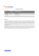
Revisions History Date Version Number Document Changes 2021/06/22 0.0 Initial Draft 2021/08/09 0.1 Statement update Disclaimer WB17 SOM are supplied “as is” and without warranties of any kind, express, implied, or statutory including, but not limited to, any implied warranty for a particular purpose. No license is granted by implication or otherwise under any patents or other intellectual property by application or use of evaluation boards.
Table of Contents 1 Overview ................................................................................................................................................................................. 5 1.1 ... General Information ......................................................................................................................................................... 5 1.2 ... Architecture and Block Diagram ..............................................................................
1 Overview 1.1 General Information WB17 i.MX8M Mini SOM is a high-performance System on Module(SOM) which is designed based on NXP®i.MX8MMini processor. i.MX8MMini integrate four ARM® Cotex-A53up to 1.8GHz and oneCotex-M4 core processor for low power processing to provide industry-leading audio voice processing for applications that scale from consumer home audio to voice assistance. It supports 1080p video encode and decode. WB17 i.
1.2 Architecture and Block Diagram Figure 1-1 WB17 SOM Block Diagram 1.3 Feature Summary NXP i.MX8M Mini CPU 1GB LPDDR4 RAM 8GB eMMC 1 x MIPI DSI 1 x MIPI CSI Wi-Fi 802.11 a/b/g/n/ac, 2x2 MIMO Bluetooth 5.x 1 x USB 2.0 OTG 1 x USB 2.0 Host 1x RGMII interface 1 x SD/MMC Serial interfaces (2 x I2C, 3 x UART, 1 x SPI, 3 x SAI) 9 x GPIOs 1x PDM 1x SPDIF www.innocomm.
1.4 Dimension The dimension of WB17 i.MX8M Mini SOM is 45mm x 42mm x 0.8mm. www.innocomm.
1.5 Electrical Specification Symbol Parameter Minimum Maximum Unit VSYS_5V5V input 2.7 NVCC_ENET_2V5 5.5 V NVCC_ENET input 2.25 2.75 V Table 1: Input Power Absolute Maximum Ratings Symbol Parameter Minimum Maximum Unit VDD_3V3 VDD_1V8 VDDIO_3V3 VDDIO_1V8 3.267 1.782 3.333 1.818 V V Table 2: Output Power Absolute Maximum Ratings IVSYS_5V Symbol Parameter Typical 5V Current 260 Maximum Unit 850 mA Table 3: Input Current Absolute Maximum Ratings 2 Main Hardware Components WB17 i.
Figure 2-1 – Top side of WB17 SOM Figure 2-2 – Bottom side of WB17 SOM www.innocomm.
2.1 CPU The i.MX8M Mini processor integrate four ARM® Cotex-A53 up to 1.8GHz and one Cotex-M4 cores to provide industry-leading audio, voice and video processing for applications. The features of i.
2.4 eMMC Storage The onboard eMMC device is connected on the SD3 pins of the i.MX 8MMini processor in an 8bit width configuration. 2.5 Wi-Fi/Bluetooth Module The WB17 adopts Murata SP-XV1XA-A combo module that integrates wireless local area network 802.11 a/b/g/n/ac2x2 MIMO and Bluetooth 5.x. www.innocomm.
3 WB17 iMX8M Mini Interfaces and Connectors WB17 use two M.2 E-key golden finger to connect with carrier board. The tables below detail the pin assignment and functionality of these connectors. 3.1 J101 Connector Table 3-1 J101 Connector J101 Pin# Signal Name i.MX8M Mini Pin # Voltage J101 Pin# Signal Name i.MX8M Mini Pin # Voltage 1 PDM_DATA3 AC13 3.3V 2 SAI1_TXFS AB19 3.3V 3 PDM_DATA1 AC14 3.3V 4 SAI1_TXD0 AG20 3.3V 5 PDM_DATA2 AD13 3.3V 6 SAI1_TXC AC18 3.
17 GND . 18 SAI1_RXD0 AG15 3.3V 19 USB1_DN A23 20 SAI1_RXFS AG16 3.3V 21 USB1_DP B23 22 SAI1_RXC AF16 3.3V 32 NVCC_ENENT_2V5 . 2.5V 34 GND . 23 GND . 33 USB1_VBUS F23 35 USB1_ID D23 5V 36 ENET_TXC AG24 3.3V 37 GPIO1_IO08 AG10 3.3V 38 GND 39 GPIO1_IO09 AF10 3.3V 40 ENET_TX_CTL AF24 3.3V 42 ENET_TD2 AG25 3.3V 44 ENET_TD3 AF25 3.3V 46 ENET_TD0 AG26 3.3V AF26 3.3V 41 GND . 43 ECSPI2_SCLK E6 45 GND 3.3V . . 47 ECSPI2_MISO A8 3.
5 PCIE_CLKP 6 SD2_nRST AB26 3.3V 7 GND 8 SD2_CMD AA27 3.3V 9 PCIE_RXN A19 3.3V 10 SD2_DATA0 AB23 3.3V 11 PCIE_RXP B19 3.3V 12 SD2_DATA1 AB24 3.3V 13 GND 14 SD2_DATA2 V24 3.3V 15 PCIE_TXN A20 3.3V 16 SD2_DATA3 V23 3.3V 17 PCIE_TXP B20 3.3V 18 SD2_nCD AA26 3.3V 19 GND 20 GND 21 USB2_DN A23 22 USB2_VBUS F23 5V 23 USB2_DP B23 32 SPDIF_TX AF9 3.3V 33 SAI2_RXD AC24 3.3V 34 BOOT_MODE0 G26 3.3V 35 SAI2_RXFS AC19 3.
3.3 Power Signals Table 4-1 Power Signal Pins Connector PIN# J101 71, 73, 75 J101 69 J101 32 Function I/O Description VSYS_5V I Input power 5V VDD_3V3 O 3.3V IO power NVCC_ENET_2V5 O 2.5V Ethernet Power 3.4 Ethernet One RGMII interface is supported. Table 4-3 Ethernet Signal Pins Connector Function PIN# J101 NVCC_ENET_2V5 21 J101 36, 40, 42,44,46, 48, 52, 56, 58, 60, 62, RGMII interface 64, 68 I/O Description O Ethernet POWER IO RGMII 3.
3.6 UARTs Each of the UART interface support the following serial data transmit/receive protocols and configurations: • • • 7- or 8-bit data words, 1 or 2 stop bits, programmable parity (even, odd or none) Programmable baud rates up to 4 Mbps. This is a higher max baud rate relative to the 1.875 MHz, which is stated by the TIA/EIA-232-F standard.
3.8 ECSPI WB17supports one full-duplex Enhanced Configurable Serial Peripheral Interface (ECSPI). The ECSPI contain a 64x32 receive buffer and a 64x32 transmit buffer. Table 4-7eSPI Signal Pins Connector PIN# J101 49 J101 47 J101 43 J101 51 Function I/O Description ECSPI2_MOSI O ECSPI2_MOSI ECSPI2_MISO I ECSPI2_MISO ECSPI2_SCLK O ECSPI2_SCLK ECSPI2_SS0 O ECSPI2_SS0 3.9 DSI Interface WB17 provides a 4-lanes MIPI display interface operating up to 1080p60 resolution.
3.10 SD/MMC Fully compatible with MMC command/response set and Physical Layer as defined in the Multimedia Card System Specification, v5.0/v4.4/v4.41/v4.4/v4.3/v4.2. • • Fully compatible with SD command/response sets and Physical Layer as defined in the SD Memory Card Specifications v 3.0 including high-capacity SDXC cards up to 2 TB. Fully compatible with SDIO command/response sets and interrupt/Read-Wait mode as defined in the SDIO Card Specification, Part E1, v. 3.
5 J102 57 J102 53 J102 55 J101 2 J101 6 J101 4 J101 9 J101 7 J101 11 J102 75 J102 73 SAI1_RXD4 I SAI1_RXD4 SAI1_RXD5 I SAI1_RXD5 SAI1_RXD6 I SAI1_RXD6 SAI1_TXFS O SAI1_TXFS SAI1_TXC O SAI1_TXC SAI1_TXD0 O SAI1_TXD0 SAI1_TXD1 O SAI1_TXD1 SAI1_TXD2 O SAI1_TXD2 SAI1_TXD3 O SAI1_TXD3 SAI1_TXD4 O SAI1_TXD4 SAI1_TXD7 O SAI1_TXD7 Table 4-13 SAI2,3,5 Signal Pins Connector PIN# J102 41 J102 37 J102 35 J102 338 J102 49 J102 47 J102 45 J102 61 J102 69 J102 67 J102 65 Function I/O D
3.12 SPDIF WB17 SOM supports Sony/Philips Digital Interface with 24-bit data width. Table 4-15 SPDIF Signal Pins Connector PIN# J101 67 J102 32 Function I/O Description SPDIF_RX I SPDIF_RX SPDIF_TX O SPDIF_TX 4 User interface Getting start The SOM can function power on 5V DC input, once system start, WB17 can use EVB HDMI output or use USB sharing to external monitor for control. www.innocomm.
You can use App for any application like play video, music etc. 5 Reference Documents 1. 2. 3. 4. i.MX 8M Family of Applications Processors Datasheet i.MX 8MMini Applications Processor Reference Manual BD71847MWV Data sheet Murata SP-XV1XA-A Combo Wi-Fi Module Datasheet www.innocomm.
Federal Communication Commission Interference Statement 15.19 This device complies with Part 15 of the FCC Rules. Operation is subject to the following two conditions: (1) this device may not cause harmful interference, and (2) this device must accept any interference received, including interference that may cause undesired operation. 15.105 This equipment has been tested and found to comply with the limits for a Class B digital device, pursuant to part 15 of the FCC Rules.
This module is intended for OEM integrators only. Per FCC KDB 996369 D03 OEM Manual v01 guidance, the following conditions must be strictly followed when using this certified module: KDB 996369 D03 OEM Manual v01 rule sections: 2.2 List of applicable FCC rules This module has been tested for compliance to FCC Part 15 2.3 Summarize the specific operational use conditions The module is tested for standalone mobile RF exposure use condition.
2.8 Label and compliance information The final end product must be labeled in a visible area with the following: “Contains FCC ID:YAIWB17”. The grantee's FCC ID can be used only when all FCC compliance requirements are met. 2.9 Information on test modes and additional testing requirements www.innocomm.
This transmitter is tested in a standalone mobile RF exposure condition and any co-located or simultaneous transmission with other transmitter(s) or portable use will require a separate class II permissive change re-evaluation or new certification. 2.10 Additional testing, Part 15 Subpart B disclaimer This transmitter module is tested as a subsystem and its certification does not cover the FCC Part 15 Subpart B (unintentional radiator) rule requirement applicable to the final host.
Industry Canada statement: This device complies with ISED’s licence-exempt RSSs. Operation is subject to the following two conditions: (1) This device may not cause harmful interference, and (2) this device must accept any interference received, including interference that may cause undesired operation. Le présent appareil est conforme aux CNR d’ ISED applicables aux appareils radio exempts de licence.
Radiation Exposure Statement: This equipment complies with ISED radiation exposure limits set forth for an uncontrolled environment. This equipment should be installed and operated with greater than 20cm between the radiator & your body. Déclaration d'exposition aux radiations: Cet équipement est conforme aux limites d'exposition aux rayonnements ISED établies pour un environnement non contrôlé. Cet équipement doit être installé et utilisé à plus de 20 cm entre le radiateur et votre corps. www.innocomm.
This device is intended only for OEM integrators under the following conditions: 1) The antenna must be installed and operated with greater than 20cm between the antenna and users, and 2) The transmitter module may not be co-located with any other transmitter or antenna. As long as 2 conditions above are met, further transmitter test will not be required.