PowerBASE ™ adjustable bed base Owners Manual www.adjustablesbyleggett.
CONTENTS Advisory.................................................................................................................................4 Acoustics...............................................................................................................................6 Installation..............................................................................................................................7 Turnbuckle Adjustment.................................................................
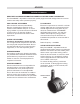
advisory important information READ THE FOLLOWING INFORMATION CAREFULLY BEFORE USING THIS PRODUCT This PowerBASE™ adjustable bed has been quality engineered with design features to assure comfort and safety when operated properly. electrical grounding This product is equipped with a polarized or grounded electrical power cord. The power cord will only fit into a grounded, electrical surge protection device (not included) or a grounded electrical outlet.
ADVISORY important information READ THE FOLLOWING INFORMATION CAREFULLY BEFORE USING THIS PRODUCT This PowerBASE™ adjustable bed has been quality engineered with design features to assure comfort and safety when operated properly. HOSPITAL use DISCLAIMER This bed is designed for in-home use only. It is not approved for hospital use and does not comply with hospital standards. Do not use this bed with tent type oxygen therapy equipment, or use near explosive gases.
acoustics lifting/lowering mechanisms The lift/lower feature will emit a minimal humming sound during operation. This is normal. During operation, the lift arm wheels make contact with the platform support of the bed. This applies slight tension on the moving components and resonance is reduced to a minimum level. If excessive noise or vibration is experienced, reverse the movement action (up or down) of the bed with the hand control.
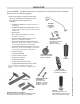
installation For PowerBASE™ installation and setup, complete the numbered procedure indicated below and on the following pages: 1. Before discarding any packing materials, check the adjustable bed shipping carton and verify the following items are included: • (1) Mattress Retainer (standard, Profile-DC, or tooless type) • (1) Mattress Retainer Hardware Kit (Tooless mattress retainer Standard type shown.
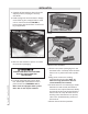
installation 2. Carefully lift the bed base frame from the shipping carton, keeping the unit topside-down. 3. Install (4) legs into the base frame. Simply screw each leg into a tapped hole at each corner of the base frame (figure 1). Insert casters into the bottom of each bed leg (if applicable). POWER DOWN BOX BATTERY COMPARTMENT DOOR casters – press-fit into bottom of legs figure 2: Power down box battery compartment door removal.
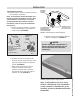
installation Standard Mattress Retainer 10. Install mattress retainer at the foot end of the bed base as follows: Note: for Profile-DC model adjustable bed mattress retainer installation, refer to Step 10a installation instructions. For tooless model adjustable bed mattress retainer installation, refer to Step 10b installation instructions. a. Install (1) cupped washer, (1) spacer and (1) flat washer on (4) mattress retainer bolts (figure 4).
installation Profile-DC Mattress Retainer 10. Install Profile-DC mattress retainer at the foot end of the bed base as follows: a. Locate (1) mattress retainer and (1) mattress retainer hardware kit (figure 7). WOODEN LOCATOR PINS mattress retainer hardware kit contains: (4) mattress retainer bolts - a (4) flat washers - b (4) retaining clips - c figure 9: Wooden locator pins mark position of the threaded lugs. a mattress retainer c b figure 7 f.
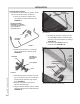
installation h. Tighten all mattress retainer bolts with a 7/16 inch wrench or socket. Note: do not overtighten. Tooless Mattress Retainer 10b. Install mattress retainer at the foot end of the bed base as follows: a. Locate grommeted holes at foot of bed base (figure 12). ed et s ommle gr ho se d ba d figure 11: Typical twin size Profile-DC shown with mattress retainer installed.
Note: It is important to position the bottom of the headboard cross member a maximum distance of 3 inches (76.2mm) between the headboard and the top of the mattress (FIGURE 15). Do not exceed 3 inches (76.2mm). X. he nc 3i A sM figure 14: Mattress retainer installed. Note: if adjustable bed is to be set up without a headboard, basic installation is now complete. If headboard is to be installed, proceed to Headboard Bracket Installation. 11. Install headboard brackets to the bed base frame*.
installation 12. Install headboard brackets to the bed base frame per the following instructions: Note: Headboard brackets are optional for Type B beds. See accessory sheet for order information. a. Raise the head section of the bed (with hand control) to gain access to the bed base frame. b. Determine bed base type (FIGURES 16 and 17). For bed base Type A, proceed to Step “e”. For bed base Type B, proceed to Step “c”. c. For bed base Type B, locate channel connector kit (FIGURE 18).
installation d. Position channel connector so that the flat side is flush against bed base frame. Attach channel connector to bed base frame using (2) 1½ inch long hex head bolts/nuts (FIGURE 20). Tighten bolts. Note: For beds with 74” base length, use inner mounting holes. For beds with 80” base length, use outer mounting holes (FIGURES 18 and 20).
installation h. When installing a headboard, footboard, or four-piece surround (case good), allow for 1.5 inches (38.1mm) to 2 inches (50.8mm) of clearance at the head and foot of the bed and a minimum of ½ inch to ¾ inch on the sides (figure 24). i. Firmly tighten the 3 inch carriage bolts of both headboard bracket channels. j. Measure the distance (center-tocenter) between the mounting holes in the headboard. k.
turnbuckle adjustment If the foot end of the bed base becomes unlevel (FIGURE 1), adjust by following the numbered instructions below. STEP 1 On one side of bed base, loosen jam nut on board end of turnbuckle assembly using a ½” wrench (FIGURE 2). Threads are right-hand threads. Repeat on other side of bed base. figure 1 foot end of bed unlevel STEP 2 On one side of bed base, loosen jam nut on carriage end of turnbuckle assembly with ½” wrench (FIGURE 3). Threads are left-hand threads.
troubleshooting In the event the PowerBASE™ adjustable bed fails to operate, investigate the symptoms and possible solutions provided in the chart below: symptom Hand control illuminates and appears to be operable, but will not activate bed. No features of the adjustable bed will activate. solution • Verify power cord is plugged into a working, grounded electrical outlet. A grounded, electrical surge protection device is recommended. Test outlet by plugging in another working appliance.
Contact customer care toll free at 800-888-3078. For customer care online, email: accustomerservice@leggett.com www.adjustablesbyleggett.