
User Manual


PowerBASE™ Owners Manual 99300787-i
15
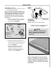
h. When installing a headboard,
footboard, or four-piece surround
(case good), allow for 1.5 inches
(38.1mm) to 2 inches (50.8mm) of
clearance at the head and foot of the
bed and a minimum of ½ inch to ¾
inch on the sides (FIGURE 24).
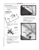
i. Firmly tighten the 3 inch carriage
bolts of both headboard bracket
channels.
j. Measure the distance (center-to-
center) between the mounting holes
in the headboard.
k. Measure the center-to-center
distance between the mounting slots
of the headboard bracket flanges
(FIGURE 25).
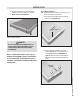
l. If bracket flange adjustment is
required to accept the headboard,
remove the
1 inch long hex
head bolts adn
move flanges
side-to-side for
the adjustment
(FIGURE 25).
Reinstall bolts.
Tighten all
headboard
mounting bolts.
m. Install
headboard.
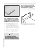
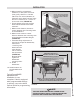
12. Install mattress on
the adjustable bed
base.
Typical PowerBASE™
adjustable bed
installation is now
complete. If bed is equipped
with programmable settings
or options, reer to the Hand
Control Guide for programming
information.
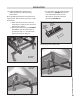
SLIDE BRACKET
ASSEMBLIES IN OR
OUT TO ACHIEVE
POSITION
1.5” to 2”
USE (2) 1 INCH LONG HEX HEAD
BOLTS TO ATTACH HEADBOARD
BRACKET FLANGE TO BRACKET
CHANNEL
HEADBOARD
BRACKET
FLANGE
FIGURE 24: Bed base Type B headboard bracket flange
attachment.
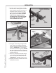
ADJUSTABLE
BED TYPE B
MEASURE FLANGE SLOTS
CENTER-TO-CENTER TO CHECK
HEADBOARD HOLE LOCATION
REMOVE 1 INCH LONG HEX HEAD BOLTS AND RELOCATE
FLANGES TO ACHIEVE CENTER-TO-CENTER DISTANCE
REQUIRED FOR HEADBOARD MOUNTING HOLES
FIGURE 25: Headboard bracket measurement and adjustment to accept
headboard.
INSTALLATION
NOTE
TWIN SIZE HEADBOARD BRACKET ASSEMBLIES ARE
SHOWN (FIGURES 23 AND 24). QUEEN SIZE HEADBOARD
BRACKETS ARE EQUIPPED WITH ANGLE BRACES.