
User Manual


PowerBASE™ Owners Manual 99300787-i
8
INSTALLATION
2. Carefully lift the bed base frame from the
shipping carton, keeping the unit top-
side-down.
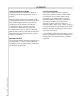
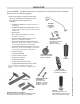
3. Install (4) legs into the base frame. Simply
screw each leg into a tapped hole at each
corner of the base frame (FIGURE 1).
Insert casters into the bottom of each bed
leg (if applicable).
CASTERS – PRESS-FIT
INTO BOTTOM OF LEGS
LEGS – SCREW INTO
TAPPED HOLE AT
EACH CORNER
FIGURE 1: Leg and caster installation.
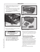
FIGURE 2: Power down box battery compartment door
removal.
4. Remove and extend out power cord from
the protective packaging.
POWER CORDS MUST NOT INTERFERE
WITH ANY ADJUSTABLE BED
MECHANISMS.
5. For beds equipped with power down
box, install (2) 9 volt batteries into the
power down box (FIGURES 2 and 3).
Note: beds not equipped with a power
down box do not require batteries.
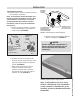
6. Remove the plastic packaging from the
bed base frame. Carefully rotate the base
frame over to position the bed top-side-
up.
7. Plug power cord into a working,
grounded electrical outlet. Note: an
electrical surge protection device is
recommended (not included).
8. If hand control is non-wired type, install
batteries in hand control (wired hand
controls do not require batteries). Briefly
activate all functions of the bed with the
hand control to verify all features are in
working order. If bed does not operate,
refer to the Troubleshooting section of
this manual.
9. Return bed to the level position.
PRESS IN (SLIGHTLY) AND
PUSH DOWN TO REMOVE
BATTERY COMPARTMENT
DOOR
POWER DOWN BOX
BATTERY COMPARTMENT DOOR
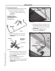
FIGURE 3: Power down box battery installation and battery
compartment door reinstallation.
BATTERY ORIENTATION IS
INDICATED INSIDE BATTERY
COMPARTMENT
DOOR REINSTALLATION:
PRESS COMPARTMENT DOOR
AGAINST THE BATTERY ENDS,
SLIDE DOOR UP AND IN TO
ENGAGE THE DOOR TABS
TABS