
User Manual


Page 4 USER MANUAL SMR-3X3 (SMR-313, SMR-323, SMR-333) Version 1.4
CONFIDENTIAL AND PROPRIETARY
The information contained in this document shall remain the sole and exclusive property of InnoSenT GmbH and shall not be
disclosed by the recipient to third parties without prior consent of InnoSenT in writing.
Experience and Reliability in Radar Technology
www.InnoSenT.de
SMR
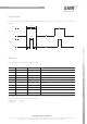
PULSE SCHEME
In order to use the pulse capability of the SMR the following scheme is recommended to avoid out of band
emissions:
3.3V
> 3µs
0V
VCC
3.3V
> 1µs
0V
1µs
1µs
enable
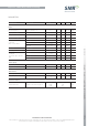
INTERFACE
The sensor provides solder pads for SMT mounting.
PIN # DESCRIPTION IN/OUT COMMENT
1 d.n.c. do not connect
2 d.n.c. do not connect
3 IF1 output signal I(nphase)
4 IF2 output signal Q(adrature)
5 enable* input TX output power enable (active high)
6 GND input analog ground
7 V
cc
input supply voltage
8 d.n.c. do not connect
9 d.n.c. do not connect
10 GND input analog ground
*the enable has no influence on current consumption rather reduces the TX output power by about 30dB. To save
power use a pulse scheme as described on page 3.
enable pin off: 0 - 0.8V
enable pin on: 2 - 3.3V