
User Manual


Page 5 USER MANUAL SMR-3X3 (SMR-313, SMR-323, SMR-333) Version 1.4
CONFIDENTIAL AND PROPRIETARY
The information contained in this document shall remain the sole and exclusive property of InnoSenT GmbH and shall not be
disclosed by the recipient to third parties without prior consent of InnoSenT in writing.
Experience and Reliability in Radar Technology
www.InnoSenT.de
SMR
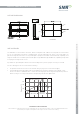
OUTLINE DIMENSIONS
antenna
antenna
TOP VIEW BOTTOM VIEW
PIN 10
PIN 6
PIN 5
PIN 1
General Tolerance
ISO 2768-mK
SMT GUIDELINES
The SMR device is 100% Pb-free. Therefore, Pb-free solder paste with a Pb-free re flow profile is recommended.
Do not use solder paste with active or acid-based flux. To avoid submerging the device in the solder paste, the
placement height (Z) of the device on the pick-and-place equipment should be controlled carefully. Optimally, the Z
height should be set at one-half the printed solder paste height. Maintaining board flatness (coplanarity) is important
in keeping the Z height under control.
If possible use a pick-and-place machine with a visions-alignment system for proper centering on the PCB.
For the soldering process we recommend the following:
• For optimum results the re flow oven should have nitrogen purge (we recommend 1000ppm)
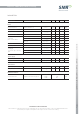
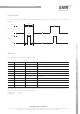
• To avoid damage during assembly solder re flow attachment, follow the guidelines in IPC/JEDEC J-STD-
020D.1. The device is qualified at 260 °C re flow. The following figure shows a typical temperature profile for
Pb-free (Sn-Ag-Cu or Sn-Ag) solder and the corresponding critical re flow parameters.
220
180
Time
Temperature (°C)
Min. 60sec
Max. 120sec
Min. 30 sec
Max. 90sec
Max. 260°C, Min 230°C
150