
User guide


Genesis II Installation Instructions
Page 50 © Mass Electronics Pty Ltd 2010Edition 2.0 dated 06/12/2013
3-4 Wiring of Remote Expansion Modules
The following paragraphs contain wiring information for the following types of Remote Expansion
Modules (REMs) used in the Genesis II System:
• GENII AI REM Analogue Input Module (3-4.3)
• GENII AO REM Analogue Output Module (3-4.4)
• GENII DI REM Dry Contact Digital Input Module (3-4.5)
• GENII DO REM Digital Output Module (3-4.6)
• GENII IDI REM Opto Isolated Digital Input Module (3-4.7)
• GENII PI REM Pulse Input Module (3-4.8)
• GENII MZS REM Multi Zone Station Module (3-4.9)
• GENII MZSAH REM Zone Control Station A/H (3-4.10)
• GENII CS REM Control Station Module (3-4.11)
• GENII CSAH REM Control Station Aer Hours Module (3-4.12)
• GENII CSFCAH REM Control Station Fan Control, Aer Hours Module (3-4.13)
• GENII MP405 Multipoint Module (3-4.14)
• GENII MP414 Multipoint Module (3-4.15)
• GENII MP423 Multipoint Module (3-4.16)
• GENII MP432 Multipoint Module (3-4.17)
• GENII Wireless Module Interface (3-4.18)
• SENRx Wireless Temperature Sensors (3-4.19)
Communication between the Genesis II Direct Digital Controller or MPCII Mid Points Controller and
REMs is by way of a RS485 cable connected between the dedicated REM network socket on the digital
controller and the REM network.
The method for connecting the modules to electrical power and to the RS485 Comms cable system
is similar for most of the dierent types of modules, except where otherwise noted. The following
two paragraphs provide detailed instructions for connecting electrical power and the RS485 system,
respectively.
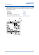
3-4.1 REM Power Connections
Power requirements are 24VAC, ±10% at 50/60 Hz. Refer to the appropriate paragraph below for the
physical location of the power connection block within each type of REM. At the power connection
block, the 24VAC power terminals are:
• Terminal 1 = 24VAC Supply
• Terminal 2 = 0VAC Supply
• Terminal 3 = Earth
Terminal 3 is for the protection of the RS485 Comms circuitry and must be connected to a good,
electrically bonded earth. This may be the earth bus bar of the switchboard or the point that
connects the chassis of the equipment the module is located in. This connection is independent of
and in addition to the earthed AC Neutral at Terminal 2.
Do not connect Terminal 3 to Terminal 2.
CAUTION