
Manual

Installation Instructions for Innotech IG04 BACnet Gateway and Vaisala Transmitter / Sensor
Page 10 © Mass Electronics Pty Ltd 2011Edition 5.0 dated 11/11/2013
Table 2: Screw Terminal Pin-outs for WXT520 / WMT52
Screw Terminal Pin RS-485
1 RX- RX-
2 RX+ RX+
3 TX- RX-
4 TX+ RX+
5 RXD
6 SGND
7 EXH
8 EXL
9 SIPB
10 SIPA
11 SR-
12 SR+
13 PT-
14 PT+
15 AGND
16 AGND
17 HTG- Vh- (heating GND)
18 HTG+ Vh+ (heating supply voltage)
19 VIN- Vin- (operating GND)
20 VIN+
Vin+ (operating supply
voltage)
Exact minimum cable specications for power supply will vary, and are installation specic. Ensure to select the correct
cable to carry the current load as required.
NOTE NOTE
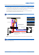
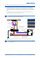
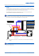
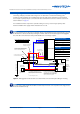
Vaisala Device Screw Terminal Pin-Outs
Please take extreme care to ensure when installing and wiring that the wire colours and terminals correctly match
as illustrated in Figure 1 or Figure 2, and described below in Table 2. Refer to the appropriate Vaisala technical
documentation for more details at www.vaisala.com.
NOTE NOTE