
Manual

Installation Instructions for Innotech IG04 BACnet Gateway and Vaisala Transmitter / Sensor
Page 9 © Mass Electronics Pty Ltd 2011Edition 5.0 dated 11/11/2013
1 2 3 4 5 6 7 8
1 2 3 4 5 6 7 8
Ethernet
&
BACIP
+
-
SHLD
-
+
Isolated DC
Power Supply
Earth Ground
Ethernet
Port &
BACnet/
IP Output
SHLD
EOL
C+
C-
SER Terminal Not Used
(Service Tool Connection)
WSP150 Surge Protector
*
1
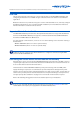
Vaisala WXT520 Weather Transmitter /
WMT52 Ultrasonic Wind Sensor
Screw Terminal connector pin-out *
1
Innotech IG04
BACnet Gateway
BLK Wire (Vin−)
RED Wire (Vin+)
24V
0V
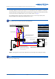
Shielded cable length should NOT exceed
3m when connecting WXT520 / WMT52
Device to WSP150 Surge Protector
If a surge protector is not installed,
connect the cables directly
RS485 [+]
S
RS485 [-]
RS485 [
Shield
]
RS485 Line
Termination
Jumper
+
-
BLU Wire (RX−)
GRY Wire (RX+)
Only used when
heating is required
YEL (Vh+)
PNK (Vh− )
RED Wire (Vin−)
BRN Wire (Vin+)
*
1
5 RXD
6 SGND
7 EXH
8 EXL
9 SIPB
10 SIPA
11 SR-
12 SR+
13 PT-
14 PT+
15 AGND
16 AGND
17 HTG-
18 HTG+
19 VIN-
20 VIN+
1 RX-
2 RX+
3 TX-
4 TX+
WXT520 / WMT52
Screw Terminals
BLU Wire (RX−)
GRY Wire (RX+)
24V to 32V DC
@ < 200mA
*
²
@ < 800mA
*
3
Note: Colour coded as per
Vaisala documentation
*
1
Wire WXT520 / WMT52 Device to the
WSP150 Surge Protector in accordance with
appropriate Vaisala technical documentation.
*
2
When heating is NOT used.
*
3
When heating IS used.
If heating is required and supplied via the
same supply wires, ensure a substantial cable
with cross-section > 1mm
2
is used to avoid
excessive voltage drops. Excessive voltage
drops may cause comms problems.
IG04 Default Settings
IP Address: 192.168.2.
S/M: 255.255.255.0
Innotech Port: 20000
BACnet/IP
BACnet Port: 47808
BACnet Instance: 1509
Baud Rate: 19200
Fault Timeout: 30 Sec
16mm² Copper Cable
HTTP Port: 80
SER
WXT
MSTP
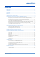
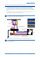
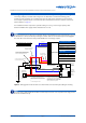
Wiring Using The Screw Terminal Connector With Split Cabling For Heating
The wiring example provided below at Figure 4 is an alternative screw terminal wiring guide,
providing a shared cabling run of suitable high capacity cable for the Vaisala device and heating
accessory (if required). The pin connections for the screw terminal connector and wire colours are
listed in Table 2 on page 10.
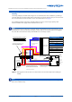
For installations that do require the optional heating accessory, ensure a high capacity cable
between the DC Power supply and the Vaisala device is used.
The screw terminal connector can be accessed from the bottom of the Vaisala device by unscrewing the three screws on
the Vaisala device's chassis, and carefully revealing the terminals. Cable runs can be fed through the small pluggable
holes in the base of the unit. Ensure to fully seal the Vaisala device once wiring is complete.
NOTE
Figure 4: Wiring guide for Vaisala device screw terminal connector with split cabling for heating
The 16mm
2
Copper Cable to Earth Ground cable is a critical component for the correct operation of the surge protector.
Ensure this is installed correctly.
NOTE
IG04 Default Settings
IP Address 192.168.2.100 (Static)
Subnet Mask 255.255.255.0
HTTP Port 80
Innotech Port 20000
BACnet/IP
BACnet Port 47808
BACnet Instance 1509
Baud Rate 19200
Fault Timeout 30 seconds