
Data Sheet


www.
inno
tec
hsm
art
.
c
om
4
-
8
Symbol
Parameter
Min
Type
Max
Unit
C
IN
Pin capacitance
-
2
-
pF
V
IN
High-level input voltage
0.75*VDD
-
VDD+0.3
V
V
IL
Low-level input voltage
-0.3
-
0.25*VDD
V
I
IH
Hight-level input current
-
-
50
nA
I
IL
Low-level input current
-
-
50
nA
V
OH
High-level output voltage
0.8VDD
-
-
V
V
OL
Low-level output voltage
-
-
0.1*VDD
V
I
OH
High-level source current (VDD =3.3V,
V
OH
≥2.64V, PAD_DRIVER = 3)
-
40
-
mA
I
OL
Low-level sink current (VDD = 3.3V, VOL =
0.495V, PAD_DRIVER = 3)
-
28
-
mA
R
PU
Resistance of internal pull-up resistor
-
45
-
kΩ
R
PD
Resistance of internal pull-down resistor
-
45
-
kΩ
V
IL_nRST
Low-level input voltage of CHIP_PU to power off
the chip
–0.3
-
0.25 × VDD
V
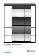
4.4 Current Consumption Characteristics
With the use of advanced power-management technologies, ESP32 can switch between different modes.
Table 5: Current Consumption Characteristics
Work mode
Description
Peak(mA)
Active
(RF working)
TX
802.11b, 20 MHz, 1 Mbps, @21 dBm
350 pending
802.11g, 20 MHz, 54 Mbps, @19 dBm
295 pending
802.11n, 20 MHz, MCS7, @18.5 dBm
290 pending
802.11n, 40 MHz, MCS7, @18.5 dBm
290 pending
RX
802.11b/g/n, HT20
82 pending
802.11n, HT40
84 pending
Note:
•
The current consumption measurements are taken with a 3.3 V supply at 25 °C of ambient temperature
at the RF port. All transmitters’ measurements are based on a 100% duty cycle.
•
The current consumption figures for in RX mode are for cases when the peripherals are disabled and the
CPU idle.
Table 6: Current Consumption De on Work Modes
Work mode
Description
Current consumption (Type)
Unit
Modem-sleep
The CPU is
Powered on
160 MHz
20
mA
80 MHz
15
mA
Light-sleep
-
130
μA
Deep-sleep
RTC timer + RTC memory
5
μA
Power off
CHIP_PU is set to low level, the chip is powered off.
1
μA
Note:
•
The current consumption figures in Modem-sleep mode are for cases where the CPU is powered on and
the cache idle.
•
When Wi-Fi is enabled, the chip switches between Active and Modem-sleep modes. Therefore, current
consumption changes accordingly.