Installation manual something new in the air 2.
We would first of all like to thank you for having chosen one of our products. We are sure you will be happy with it because it represents the state of the art in the technology of home air conditioning. By following the suggestions contained in this manual, the product you have purchased will operate without problems, giving you optimum room temperatures with minimum energy costs. Innova S.r.
1 General 1 General warnings . . . . . . . . . . . . . . . . . . . . . . . . . . . . . . . . . . . . . . . . . . . . . . . . . . . . . . . . . . . . . . . . 4 2 Fundamental safety rules . . . . . . . . . . . . . . . . . . . . . . . . . . . . . . . . . . . . . . . . . . . . . . . . . . . . . . . . . . 4 3 Description . . . . . . . . . . . . . . . . . . . . . . . . . . . . . . . . . . . . . . . . . . . . . . . . . . . . . . . . . . . . . . . . . . . . 5 4 Storage . . . . . . . . . . . . . . . . . .
GENERAL 1.1 General warnings After unpacking, check that the contents are intact and that all parts are included. If not, contact the agent who sold the appliance to you. The appliance must be installed by an authorised company. Once the work is done, it must issue a declaration of conformity to the client in compliance with current regulations and with the indications in the instruction manual supplied y the manufacturer with the appliance.
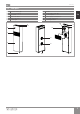
GENERAL U I S 1.3 Description The air conditioning unit "2.0" is the new solution that represents a significant step towards reducing the aesthetic impact of air conditioners. With a depth of just 16 centimetres, "2.0" is the most compact and least bulky of the category. Its aesthetic impact is therefore minimal, both inside and out. Optimised Capacities The conditioning capacities of "2.
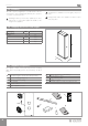
GENERAL 1.5 U I S Handling The unit is packed singularly in a cardboard box. Boxes can either be carried singularly by hand by two operators or loaded on a transport cart.. The appliance is unbalanced on the right (compressor side) During transportation, the appliance must be kept in vertical position. Handling must be performed by qualified personnel, with specific tools and with equipment suitable for the weight of the appliance. 1.6 Shipping dimensions and weight Packaging M.E. 2.
GENERAL U I S 1.
INSTALLATION U I S INSTALLATION 2.1 Installation method Before installing the conditioner, it is essential to calculate the summer thermal loads (and winter ones for the models with a heat pump) of the room. The more exact the calculation, the better the product will work. Please refer to current regulations to carry out calculations. For large-scale installations, please call a specialised heat engineer firm. Therefore, try to reduce higher heat loads by following instructions below: 2.
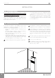
INSTALLATION U I S 2.3 Assembling the unit For the unit to work, two holes Ø162 must be placed as indicated on the template; A hole is also indicated on the template to secure the appliance on the wall with an anti-lifting bracket, which is already on the appliance. The maximum length of the holes is 1 m and there must be no bends. Use the supplied grids or grids with the same characteristics.
INSTALLATION 2.4 U I S Condensation drain preparation For heat pump appliances, a condensation drain pipe (internal Ø16 mm, not supplied) must connect the unit to the pipe on the rear of the appliance. A solenoid valve will start the flow of the condensation from the internal collection tray when the maximum level has been reached. For cooling only appliances, this pipe must be connected if the appliance is intended for use with low external temperatures (below 23°C). Drainage occurs by gravity.
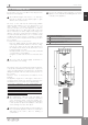
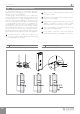
INSTALLATION U I S Insulation of the internal condensation drain pipe NB: when laying the condensation drain pipe towards the outside, the internal pipe supplied with the appliance should be lined with anti-condensation insulating material with an internal diameter of 10 mm (see point 2 in the diagram). The insulating material should be fitted up to the mouth of the external condensation drain pipe fixed in the wall. 1 Wall section 4 External condensation drain pipe 2 Insulation A 2.
INSTALLATION 2.6 U I S Assembling air ducts and external shutters Once the holes have been made, place the supplied plastic sheets inside them. Roll up the sheet and insert it in the hole, checking that the A junction line is aiming upwards. Use a cutter to remove any excess pipe.
INSTALLATION U I S 2.7 Mounting the appliance on the bracket After checking that the bracket is anchored to the wall and that all necessary electrical connections and condensation drain preparations have been made, you can mount the conditioner. Lift it by the sides of the bottom base until the bracket fits on all of the right spots on the appliance. In order to ease the operation, slightly tilt the appliance towards you.
INSTALLATION U I S CP occupancy contact input connection When the CP contact opens (very low voltage, connected to a free non-live contact) the appliance is put is stand-by and CP appears on the display. Using this contact, it is possible to connect an external device that inhibits the functioning of the appliance such as: open window contact, on/off remote, infrared presence sensors, enabling badge, etc. We recommend using a double insulation cable.
INSTALLATION U I S 2.13 Detecting possible faults If the conditioner blocks because of an alarm (see following table), please communicate to the assistance centre the code on the display to facilitate interventions.
MAINTENANCE U I S MAINTENANCE 3.1 Periodic Maintenance The air conditioner you have bought has been designed to keep maintenance operations to a minimum, in fact, they only include the following cleaning operations: External cleaning Disconnect the unit from the power supply before each cleaning and maintenance intervention by setting the main power supply switch to off. Wait for the components to cool down in order to avoid any burns. Pay attention to the sharp edges.
MAINTENANCE U I S 3.2 Troubleshooting In the even of a malfunction, please refer to the following table. If, after performing the suggested checks, the problem is not solved, Fault please contact the authorised technical assistance. EN Possible causes The appliance doesn't switch on The appliance does not cool/heat adequately. Solution Check there is power supply (by turning a light on, for example).
MAINTENANCE 3.3 U I S Technical specifications Please read data plate to obtain the technical data listed below. Power supply voltage Maximum absorbed power Maximum absorbed current Amount of refrigerant gas Casing protection rating U.M. 10 HP DC Inverter 12 HP DC Inverter Cooling power (1) kW 2.04 2.35 Power in max cooling mod. Dual Power kW 2.60 3.11 Power in min cooling mod. Dual Power kW 0.81 0.92 Heating power (2) kW 2.10 2.36 Heating power (3) kW 0.98 1.
U I S NOTES EN 19
realised with iés technology by INNOVA s.r.l. s.r. l . FrazI Maggio Via . St rada, 8 16 - 38089 - 38085 STORO PIEVE(TN) DI BONO - ITALY(TN) - ITALY tel. +39.0465.670104 fax +39.0465.674965 info@innovaenergie.com N420036A N273027A- -Rev. Rev.