Table of Contents INTRODUCTION WHAT IS OBD? ............................................................................................................................................. YOU CAN DO IT! ......................................................................................................................................................... SAFETY PRECAUTIONS SAFETY FIRST! ............................................................................................................................
Introduction WHAT IS OBD? WHAT IS OBD? The FixAssist® Scan Tool is designed to work on all OBD2 compliant vehicles. All 1996 and newer vehicles (cars, light trucks and SUVs) sold in the United States are OBD2 compliant. One of the most exciting improvements in the automobile industry was the addition of onboard diagnostics (OBD) on vehicles, or in more basic terms, the computer that activates the vehicle’s “CHECK ENGINE” light.
You Can Do It! EASY TO USE - EASY TO VIEW - EASY TO DEFINE Easy To Use . . . . Connect the Scan Tool to the vehicle’s test connector. Turn the ignition key "On.” The tool will automatically link to the vehicle’s computer. Easy To View . . . . The Scan Tool retrieves stored codes, Freeze Frame data and I/M Readiness Status. Codes, I/M Readiness Status and Freeze Frame data are displayed on the Scan Tool’s display screen. System Status is indicated by LED indicators. Easy To Define . . .
Safety Precautions SAFETY FIRST! SAFETY FIRST! To avoid personal injury, instrument damage and/or damage to your vehicle; do not use the FixAssist® Scan Tool before reading this manual. This manual describes common test procedures used by experienced service technicians. Many test procedures require precautions to avoid accidents that can result in personal injury, and/or damage to your vehicle or test equipment.
Safety Precautions SAFETY FIRST! To prevent damage to the on-board computer when taking vehicle electrical measurements, always use a digital multimeter with at least 10 megOhms of impedance. Fuel and battery vapors are highly flammable. To prevent an explosion, keep all sparks, heated items and open flames away from the battery and fuel / fuel vapors. DO NOT SMOKE NEAR THE VEHICLE DURING TESTING. Don't wear loose clothing or jewelry when working on an engine.
About the Scan Tool VEHICLES COVERED VEHICLES COVERED The FixAssist® Scan Tool is designed to work on all OBD2 compliant vehicles. All 1996 and newer vehicles (cars and light trucks) sold in the United States are OBD2 compliant. Federal law requires that all 1996 and newer cars and light trucks sold in the United States must be OBD2 compliant; this includes all Domestic, Asian and European vehicles. Some 1994 and 1995 vehicles are OBD2 compliant.
About the Scan Tool BATTERY REPLACEMENT On some Asian and European vehicles the DLC is located behind the “ashtray” (the ashtray must be removed to access it) or on the far left corner of the dash. If the DLC cannot be located, consult the vehicle’s service manual for the location. BATTERY REPLACEMENT Replace batteries when the battery symbol is visible on display and/or the 3 LEDS are all lit and no other data is visible on screen. 1. Locate the battery cover on the back of the Scan Tool. 2.
Scan Tool Controls CONTROLS AND INDICATORS CONTROLS AND INDICATORS 14 13 11 12 10 7 1 2 4 5 3 6 8 9 20 15 16 17 18 19 Figure 1. Controls and Indicators See Figure 1 for the locations of items 1 through 20, below. 1. ERASE button - Erases Diagnostic Trouble Codes (DTCs), and “Freeze Frame” data from your vehicle’s computer, and resets Monitor status. 2. SYSTEM MENU button – When pressed, displays the System Test Menu. 3.
Scan Tool Controls CONTROLS AND INDICATORS 8. ENTER button - When in MENU mode, confirms the selected option or value. 9. DOWN button - When in MENU mode, scrolls DOWN through the menu and submenu selection options. When LINKED to a vehicle, scrolls DOWN through the current display screen to display any additional data. 10. GREEN LED - Indicates that all engine systems are running normally (all Monitors on the vehicle are active and performing their diagnostic testing, and no DTCs are present). 11.
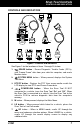
Scan Tool Controls DISPLAY FUNCTIONS DISPLAY FUNCTIONS 2 1 15 3 4 5 6 11 12 7 13 8 9 10 14 Figure 2. Display Functions See Figure 2 for the locations of items 1 through 14, below. 1. I/M MONITOR STATUS field - Identifies the I/M Monitor status area. 2. Monitor icons - Indicate which Monitors are supported by the vehicle under test, and whether or not the associated Monitor has run its diagnostic testing (Monitor status).
Scan Tool Controls DISPLAY FUNCTIONS 7. DTC Display Area - Displays the Diagnostic Trouble Code (DTC) number. Each fault is assigned a code number that is specific to that fault. The DTC number is color-coded as follows: RED - Indicates the currently displayed DTC is a PERMANENT DTC. YELLOW - Indicates the currently displayed DTC is a PENDING DTC. GREEN - In cases where no codes are retrieved, a “No DTCs are presently stored in the vehicle’s computer” message is shown in green. 8.
Onboard Diagnostics COMPUTER ENGINE CONTROLS COMPUTER ENGINE CONTROLS The Introduction of Electronic Engine Controls Electronic Computer Control Systems make it possible for vehicle manufacturers to comply with the tougher emissions and fuel efficiency standards mandated by State and Federal Governments.
Onboard Diagnostics COMPUTER ENGINE CONTROLS The Basic Engine Computer Control System The Computer Control System consists of an on-board computer and several related control devices (sensors, switches, and actuators). The on-board computer is the heart of the Computer Control System. The computer contains several programs with preset reference values for air/fuel ratio, spark or ignition timing, injector pulse width, engine speed, etc.
Onboard Diagnostics COMPUTER ENGINE CONTROLS Vehicle operating conditions are constantly changing. The computer continuously makes adjustments or corrections (especially to the air/fuel mixture and spark timing) to keep all the engine systems operating within the preset reference values. On-Board Diagnostics - First Generation (OBD1) With the exception of some 1994 and 1995 vehicles, most vehicles from 1982 to 1995 are equipped with some type of first generation On-Board Diagnostics.
Onboard Diagnostics COMPUTER ENGINE CONTROLS Because OBD1 systems only detect failed components, the degraded components were not setting codes. Some emissions problems related to degraded components only occur when the vehicle is being driven under a load. The emission checks being conducted at the time were not performed under simulated driving conditions. As a result, a significant number of vehicles with degraded components were passing Emissions Tests.
Onboard Diagnostics COMPUTER ENGINE CONTROLS Powertrain Control Module (PCM) - The PCM is the OBD2 accepted term for the vehicle’s “on-board computer.” In addition to controlling the engine management and emissions systems, the PCM also participates in controlling the powertrain (transmission) operation. Most PCMs also have the ability to communicate with other computers on the vehicle (ABS, ride control, body, etc.). Monitor - Monitors are “diagnostic routines” programmed into the PCM.
Onboard Diagnostics DIAGNOSTIC TROUBLE CODES (DTCs) OBD2 Drive Cycle - An OBD2 Drive Cycle is an extended set of driving procedures that takes into consideration the various types of driving conditions encountered in real life. These conditions may include starting the vehicle when it is cold, driving the vehicle at a steady speed (cruising), accelerating, etc.
Onboard Diagnostics DIAGNOSTIC TROUBLE CODES (DTCs) Manufacturer-Specific DTCs are codes that are controlled by the vehicle manufacturers. The Federal Government does not require vehicle manufacturers to go beyond the standardized generic DTCs in order to comply with the new OBD2 emissions standards. However, manufacturers are free to expand beyond the standardized codes to make their systems easier to diagnose. The 3rd character is a letter or a numeric digit (0 thru 9, A thru F).
Onboard Diagnostics DIAGNOSTIC TROUBLE CODES (DTCs) DTCs and MIL Status When the vehicle’s on-board computer detects a failure in an emissions-related component or system, the computer’s internal diagnostic program assigns a diagnostic trouble code (DTC) that points to the system (and subsystem) where the fault was found. The diagnostic program saves the code in the computer’s memory.
Onboard Diagnostics OBD2 MONITORS If the conditions that caused the MIL to light are no longer present for the next three trips in a row, the computer automatically turns the MIL “Off” if no other emissions-related faults are present. However, the DTCs remain in the computer’s memory as a history code for 40 warm-up cycles (80 warm-up cycles for fuel and misfire faults). The DTCs are automatically erased if the fault that caused them to be set is not detected again during that period.
Onboard Diagnostics OBD2 MONITORS Non-Continuous Monitors The other twelve Monitors are “non-continuous” Monitors. “Noncontinuous” Monitors perform and complete their testing once per trip. The “non-continuous” Monitors are: Oxygen Sensor Monitor Oxygen Sensor Heater Monitor Catalyst Monitor Heated Catalyst Monitor EGR System Monitor EVAP System Monitor Secondary Air System Monitor The following Monitors became standard beginning in 2010.
Onboard Diagnostics OBD2 MONITORS Fuel System Monitor - This Monitor uses a Fuel System Correction program, called Fuel Trim, inside the on-board computer. Fuel Trim is a set of positive and negative values that represent adding or subtracting fuel from the engine. This program is used to correct for a lean (too much air/not enough fuel) or rich (too much fuel/not enough air) air-fuel mixture. The program is designed to add or subtract fuel, as needed, up to a certain percent.
Onboard Diagnostics OBD2 MONITORS the downstream sensor signal voltage becomes almost the same as the upstream sensor signal. In this case, the monitor fails the test. The Catalyst Monitor is supported by “spark ignition” vehicles only. The Catalyst Monitor is a “Two-Trip” Monitor. If a fault is found on the first trip, the computer temporarily saves the fault in its memory as a Pending Code. The computer does not command the MIL on at this time.
Onboard Diagnostics OBD2 MONITORS valve to allow engine vacuum to draw the fuel vapors from the canister into the engine where the vapors are burned. The EVAP Monitor checks for proper fuel vapor flow to the engine, and pressurizes the system to test for leaks. The computer runs this Monitor once per trip. The EVAP Monitor is supported by “spark ignition” vehicles only. The EVAP Monitor is a “Two-Trip” Monitor.
Onboard Diagnostics OBD2 MONITORS oxygen sensor reacts quickly to any change in oxygen content in the exhaust stream. A faulty oxygen sensor reacts slowly, or its voltage signal is weak or missing. The Oxygen Sensor Monitor is supported by “spark ignition” vehicles only. The Oxygen Sensor Monitor is a “Two-Trip” monitor. If a fault is found on the first trip, the computer temporarily saves the fault in its memory as a Pending Code. The computer does not command the MIL on at this time.
Onboard Diagnostics OBD2 MONITORS NOx Aftertreatment Monitor - NOx aftertreatment is based on a catalytic converter support that has been coated with a special washcoat containing zeolites. NOx Aftertreatment is designed to reduce oxides of nitrogen emitted in the exhaust stream. The zeolite acts as a molecular "sponge" to trap the NO and NO2 molecules in the exhaust stream. In some implementations, injection of a reactant before the aftertreatment purges it.
Onboard Diagnostics OBD2 MONITORS PM Filter Monitor - The particulate matter (PM) filter removes particulate matter from the exhaust stream by filtration. The filter has a honeycomb structure similar to a catalyst substrate, but with the channels blocked at alternate ends. This forces the exhaust gas to flow through the walls between the channels, filtering the particulate matter out.
Onboard Diagnostics OBD2 MONITORS Name of Monitor A B C D E F Comprehensive Component Monitor Continuous 1 2 1 3 40 Misfire Monitor (Type 1 and 3) Continuous 1 2 1 3 - similar conditions 80 Misfire Monitor (Type 2) Continuous 1 3 - similar conditions 80 80 Fuel System Monitor Continuous 1 1 or 2 1 3 - similar conditions Catalytic Converter Monitor Once per trip 1 2 1 3 trips 40 Oxygen Sensor Monitor Once per trip 1 2 1 3 trips 40 Oxygen Sensor Heater Monitor O
Preparation for Testing PRELIMINARY VEHICLE DIAGNOSTIC WORKSHEET PRELIMINARY VEHICLE DIAGNOSTIC WORKSHEET The purpose of this form is to help you gather preliminary information on your vehicle before you retrieve codes. By having a complete account of your vehicle's current problem(s), you will be able to systematically pinpoint the problem(s) by comparing your answers to the fault codes you retrieve.
Preparation for Testing PRELIMINARY VEHICLE DIAGNOSTIC WORKSHEET WHEN DID YOU FIRST NOTICE THE PROBLEM: Just Started Started Last Week Started Last Month Other: m LIST ANY REPAIRS DONE IN THE PAST SIX MONTHS: PROBLEMS STARTING No symptoms Cranks, but will not start Starts, but takes a long time Right after vehicle comes to a stop Will not crank ENGINE QUITS OR STALLS No symptoms Right after starting When shifting into gear While idling During steady-speed
Preparation for Testing PRELIMINARY VEHICLE DIAGNOSTIC WORKSHEET AUTOMATIC TRANSMISSION PROBLEMS (if applicable) No symptoms Shifts too early or too late Changes gear incorrectly PROBLEM OCCURS Morning Vehicle does not move when in gear Jerks or bucks Afternoon Anytime Hot ENGINE TEMPERATURE WHEN PROBLEM OCCURS Cold Warm DRIVING CONDITIONS WHEN PROBLEM OCCURS Short - less than 2 miles 2 - 10 miles Long - more than 10 miles Stop and go While turning Wh
Preparation for Testing BEFORE YOU BEGIN BEFORE YOU BEGIN The FixAssist® Scan Tool aids in monitoring electronicand emissions-related faults in your vehicle and retrieving fault codes related to malfunctions in these systems. Mechanical problems such as low oil level or damaged hoses, wiring or electrical connectors can cause poor engine performance and may also cause a fault code to set. Fix any known mechanical problems before performing any test.
Preparation for Testing VEHICLE SERVICE MANUALS VEHICLE SERVICE MANUALS Always refer to the manufacturer’s service manual for your vehicle before performing any test or repair procedures. Contact your local car dealership, auto parts store or bookstore for availability of these manuals. The following companies publish valuable repair manuals: Haynes Publications 861 Lawrence Drive Newbury Park, California 91320 Phone: 800-442-9637 Web: www.haynes.
Using the Scan Tool CODE RETRIEVAL PROCEDURE CODE RETRIEVAL PROCEDURE Retrieving and using Diagnostic Trouble Codes (DTCs) for troubleshooting vehicle operation is only one part of an overall diagnostic strategy. Never replace a part based only on the DTC definition. Each DTC has a set of testing procedures, instructions and flow charts that must be followed to confirm the location of the problem. This information is found in the vehicle's service manual.
Using the Scan Tool CODE RETRIEVAL PROCEDURE If replacing the fuse(s) does not correct the problem, consult your vehicle’s repair manual to identify the proper computer (PCM) fuse/circuit, and perform any necessary repairs before proceeding. 6. The Scan Tool will automatically start a check of the vehicle’s computer to determine which type of communication protocol it is using. When the Scan Tool identifies the computer’s communication protocol, a communication link is established.
Using the Scan Tool CODE RETRIEVAL PROCEDURE If the information shown is correct for the vehicle under test, use and DOWN buttons, as necessary, to highlight the UP Yes, then press the ENTER button. Proceed to step 10. If the information shown is not correct for the vehicle under text, or if you wish to manually select the vehicle, use UP and DOWN buttons, as necessary, to highlight No, then press button. Proceed to step 8.
Using the Scan Tool CODE RETRIEVAL PROCEDURE Use the UP and DOWN buttons, as necessary, to highlight the desired vehicle model, then press the ENTER button to continue. If necessary, select Next to view additional options. - The Select displays. Engine screen Use the UP and DOWN buttons, as necessary, to highlight the desired vehicle engine size, then press the ENTER button to continue. If necessary, select Next to view additional options. - The Select Transmission screen displays.
Using the Scan Tool CODE RETRIEVAL PROCEDURE Refer to DISPLAY FUNCTIONS on page 8 for a description of display elements. If a recommended solution for the "priority" DTC is available, the FixAssist® screen for the DTC displays. The screen shows recommended inspection and repair actions to correct the malfunction that caused the DTC to be set. If a recommended solution for the “priority” DTC is not available, an advisory message displays. Press the DTC/FF button to scroll to the next DTC.
Using the Scan Tool CODE RETRIEVAL PROCEDURE The green, yellow and red LEDs are used (with the display) as visual aids to make it easier to determine engine system conditions. Green LED – Indicates that all engine systems are “OK” and operating normally. All monitors supported by the vehicle have run and performed their diagnostic testing, and no trouble codes are present. All Monitor icons will be solid. Yellow LED – Indicates one of the following conditions: A.
Using the Scan Tool CODE RETRIEVAL PROCEDURE DTC’s that start with “P1” and some “P3” are Manufacturer specific codes and their code definitions vary with each vehicle manufacturer. 13. If more than one DTC was retrieved, and to view Freeze Frame Data, press and release the DTC/FF button, as necessary. Each time the DTC/FF button is pressed and released, the Scan Tool will scroll and display the next DTC in sequence until all DTCs in its memory have displayed.
Using the Scan Tool THE SYSTEM MENU - VIEWING OEM ENHANCED DTCs THE SYSTEM MENU The System Menu provides the ability to retrieve “enhanced” DTCs and Anti-Lock Brake System (ABS) DTCs for most BMW, Chrysler/Jeep, Ford/Mazda, GM/Isuzu, Honda/Acura, Hyundai, Mercedes Benz, Nissan, Toyota/Lexus, Volkswagen and Volvo vehicles. The types of enhanced data available depends on the vehicle make. You can also access an “Oil Maintenance Light” reset function, and return to the Global OBD2 mode.
Using the Scan Tool VIEWING OEM ENHANCED DTCs 1. A “One moment please” message displays while the Scan Tool retrieves the selected DTCs. If the Scan Tool fails to link to the vehicle’s computer, a “Communication Error” message shows on the Scan Tool’s display. - Ensure your vehicle is OBD2 compliant. See VEHICLES COVERED on page 5 for vehicle compliance verification information. - Verify the connection at the DLC, and verify the ignition is ON.
Using the Scan Tool VIEWING OEM ENHANCED DTCs I/M MONITOR STATUS icons are not displayed when viewing enhanced DTCs. In the case of long code definitions, a small arrow is shown in the upper/lower right-hand corner of the code display area to indicate the presence of additional information. Use the UP and DOWN buttons, as necessary, to view the additional information. The Scan Tool will display a code only if codes are present in the vehicle’s computer memory.
Using the Scan Tool VIEWING OEM ENHANCED DTCs If the Scan Tool fails to link to the vehicle’s computer, a “Communication Error” message shows on the Scan Tool’s display. - Ensure your vehicle is OBD2 compliant. See VEHICLES COVERED on page 5 for vehicle compliance verification information. - Verify the connection at the DLC, and verify the ignition is ON. - Turn the ignition OFF, wait 5 seconds, then back ON to reset the computer. - Press the POWER/LINK button to continue.
Using the Scan Tool VIEWING OEM ENHANCED DTCs In the case of long code definitions, a small arrow is shown in the upper/lower right-hand corner of the code display area to indicate the presence of additional information. Use the UP and DOWN buttons, as necessary, to view the additional information. The Scan Tool will display a code only if codes are present in the vehicle’s computer memory. If no codes are present, a “No OEM Enhanced DTC’s are presently stored in the vehicle’s computer” is displayed.
Using the Scan Tool VIEWING OEM ENHANCED DTCs 2. If KOEO or Continuous Memory is selected, an “instructional” message shows on the Scan Tool’s display. Turn the ignition OFF, then back button. ON. Press the ENTER Proceed to step 3. 3. A “One moment please” message displays while the test is in progress. If the Scan Tool fails to link to the vehicle’s computer, a “Communication Error” message shows on the Scan Tool’s display. - Ensure your vehicle is OBD2 compliant.
Using the Scan Tool VIEWING OEM ENHANCED DTCs 4. If the KOER test was selected, an “instructional” message shows on the Scan Tool’s display. Turn the steering wheel to the right, then release. Press and release the brake pedal. Cycle the equipped). A “One moment please” message displays while the test is in progress. overdrive switch (if 5. To read the display: Refer to DISPLAY FUNCTIONS on page 8 for a description of LCD display elements.
Using the Scan Tool VIEWING OEM ENHANCED DTCs 6. If more than one code was retrieved press the DTC/FF button, as necessary, to display additional codes one at a time. Whenever the Scroll function is used to view additional codes, the Scan Tool’s communication link with the vehicle’s computer disconnects. To re-establish communication, press the POWER/LINK button again. 7. When the last retrieved DTC has been displayed and the DTC/FF button is pressed, the Scan Tool returns to the “Priority” Code.
Using the Scan Tool VIEWING OEM ENHANCED DTCs - Contact Technical Support for assistance. 2. To read the display: Refer to DISPLAY FUNCTIONS on page 8 for a description of LCD display elements. A visible icon indicates that the Scan Tool is being powered through the vehicle’s DLC connector. The upper left corner of the display shows the Diagnostic Trouble Code (DTC), the number of the code currently being displayed and the total number of codes retrieved, and the type of code.
Using the Scan Tool VIEWING OEM ENHANCED DTCs To exit the enhanced mode, press the SYSTEM MENU button to return to the System Menu. Use the UP and buttons, as necessary, to highlight Global OBD, then DOWN button to return to the Global OBD2 mode. press the ENTER Honda/Acura Enhanced DTCs When Honda OEM Enhanced is chosen from the System Menu, the Scan Tool retrieves OEM enhanced DTCs from the vehicle’s computer. 1. A “One moment please” message displays while the Scan Tool retrieves the selected DTCs.
Using the Scan Tool VIEWING OEM ENHANCED DTCs The upper left corner of the display shows the Diagnostic Trouble Code (DTC), the number of the code currently being displayed and the total number of codes retrieved, and the type of code. The related code definition is shown in the lower section of the LCD display. If the definition for the currently displayed code is not available, an advisory message shows on the Scan Tool’s LCD display.
Using the Scan Tool VIEWING OEM ENHANCED DTCs Hyundai Enhanced DTCs When Hyundai OEM Enhanced is chosen from the System Menu, the Scan Tool retrieves OEM enhanced DTCs from the vehicle’s computer. 1. A “One moment please” message displays while the Scan Tool retrieves the selected DTCs. If the Scan Tool fails to link to the vehicle’s computer, a “Communication Error” message shows on the Scan Tool’s display. - Ensure your vehicle is OBD2 compliant.
Using the Scan Tool VIEWING OEM ENHANCED DTCs If the definition for the currently displayed code is not available, an advisory message shows on the Scan Tool’s LCD display. I/M MONITOR STATUS icons are not displayed when viewing enhanced DTCs. In the case of long code definitions, a small arrow is shown in the upper/lower right-hand corner of the code display area to indicate the presence of additional information. Use the UP and DOWN buttons, as necessary, to view the additional information.
Using the Scan Tool VIEWING OEM ENHANCED DTCs If the Scan Tool fails to link to the vehicle’s computer, a “Communication Error” message shows on the Scan Tool’s display. - Ensure your vehicle is OBD2 compliant. See VEHICLES COVERED on page 5 for vehicle compliance verification information. - Verify the connection at the DLC, and verify the ignition is ON. - Turn the ignition OFF, wait 5 seconds, then back ON to reset the computer. - Press the POWER/LINK button to continue.
Using the Scan Tool VIEWING OEM ENHANCED DTCs In the case of long code definitions, a small arrow is shown in the upper/lower right-hand corner of the code display area to indicate the presence of additional information. Use the UP and DOWN buttons, as necessary, to view the additional information. The Scan Tool will display a code only if codes are present in the vehicle’s computer memory. If no codes are present, a “No OEM Enhanced DTC’s are presently stored in the vehicle’s computer” is displayed.
Using the Scan Tool VIEWING OEM ENHANCED DTCs - Press the POWER/LINK button to continue. If the Scan Tool cannot link to the vehicle’s computer after three attempts, the message “Contact Technical Support” displays. - Press the SYSTEM MENU button to return to the System Menu. - Turn the ignition off, disconnect the Scan Tool. and - Contact Technical Support for assistance. 2. To read the display: Refer to DISPLAY FUNCTIONS on page 8 for a description of LCD display elements.
Using the Scan Tool VIEWING OEM ENHANCED DTCs 3. If more than one code was retrieved press the DTC/FF button, as necessary, to display additional codes one at a time. Whenever the Scroll function is used to view additional codes, the Scan Tool’s communication link with the vehicle’s computer disconnects. To re-establish communication, press the POWER/LINK button again. 4. When the last retrieved DTC has been displayed and the DTC/FF button is pressed, the Scan Tool returns to the “Priority” Code.
Using the Scan Tool VIEWING OEM ENHANCED DTCs - Contact Technical Support for assistance. 2. To read the display: Refer to DISPLAY FUNCTIONS on page 8 for a description of LCD display elements. A visible icon indicates that the Scan Tool is being powered through the vehicle’s DLC connector. The upper left corner of the display shows the Diagnostic Trouble Code (DTC), the number of the code currently being displayed and the total number of codes retrieved, and the type of code.
Using the Scan Tool VIEWING OEM ENHANCED DTCs To exit the enhanced mode, press the SYSTEM MENU button to return to the System Menu. Use the UP and buttons, as necessary, to highlight Global OBD, then DOWN press the ENTER button to return to the Global OBD2 mode. Volkswagen Enhanced DTCs When Volkswagen OEM Enhanced is chosen from the System Menu, the Scan Tool retrieves OEM enhanced DTCs from the vehicle’s computer. 1.
Using the Scan Tool VIEWING OEM ENHANCED DTCs The upper left corner of the display shows the Diagnostic Trouble Code (DTC), the number of the code currently being displayed and the total number of codes retrieved, and the type of code. The related code definition is shown in the lower section of the LCD display. If the definition for the currently displayed code is not available, an advisory message shows on the Scan Tool’s LCD display.
Using the Scan Tool VIEWING OEM ENHANCED DTCs Volvo Enhanced DTCs When Volvo OEM Enhanced is chosen from the System Menu, the Scan Tool retrieves OEM enhanced DTCs from the vehicle’s computer. 1. A “One moment please” message displays while the Scan Tool retrieves the selected DTCs. If the Scan Tool fails to link to the vehicle’s computer, a “Communication Error” message shows on the Scan Tool’s display. - Ensure your vehicle is OBD2 compliant.
Using the Scan Tool VIEWING ABS DTCs If the definition for the currently displayed code is not available, an advisory message shows on the Scan Tool’s LCD display. I/M MONITOR STATUS icons are not displayed when viewing enhanced DTCs. In the case of long code definitions, a small arrow is shown in the upper/lower right-hand corner of the code display area to indicate the presence of additional information. Use the UP and DOWN buttons, as necessary, to view the additional information.
Using the Diagnostic Tool VIEWING ABS DTCs If ABS functionality is not supported by the vehicle under test, an advisory message shows on the Scan Tool’s display. Press the button to return SYSTEM MENU to the System Menu. If the Scan Tool fails to link to the vehicle’s computer, a "Communication Error" message shows on the Scan Tool’s display. - Ensure your vehicle is OBD2 compliant. See VEHICLES COVERED on page 5 for vehicle compliance verification information.
Using the Scan Tool ERASING DIAGNOSTIC TROUBLE CODES (DTCs) If the definition for the currently displayed code is not available, an advisory message shows on the Scan Tool’s LCD display. I/M MONITOR STATUS icons are not displayed when viewing ABS DTCs. In the case of long code definitions, a small arrow is shown in the upper/lower right-hand corner of the code display area to indicate the presence of additional information. Use the UP and DOWN buttons, as necessary, to view the additional information.
Using the Scan Tool ERASING DIAGNOSTIC TROUBLE CODES (DTCs) When DTCs are erased from the vehicle's computer memory, the I/M Readiness Monitor Status program resets the status of all Monitors to a not run "flashing" condition. To set all of the Monitors to a DONE status, an OBD2 Drive Cycle must be performed. Refer to your vehicle's service manual for information on how to perform an OBD2 Drive Cycle for the vehicle under test. 1.
Using the Scan Tool I/M READINESS TESTING If the erase was successful, a confirmation message shows on the display. Press the SYSTEM MENU button to return to the System Menu. If the erase was not successful and ECU error code $22 is present, an advisory message displays. Start the engine and maintain vehicle speed at 0, then press the ERASE button to try again. If the erase was not successful, an advisory message shows on the display indicating the erase request was sent to the vehicle’s computer.
Using the Scan Tool I/M READINESS TESTING I/M Readiness Monitors I/M Readiness shows whether the various emissions-related systems on the vehicle are operating properly and are ready for Inspection and Maintenance testing. State and Federal Governments enacted Regulations, Procedures and Emission Standards to ensure that all emissions-related components and systems are continuously or periodically monitored, tested and diagnosed whenever the vehicle is in operation.
Using the Scan Tool I/M READINESS TESTING Performing I/M Readiness Quick Check When a vehicle first comes from the factory, all Monitors indicate a “HAVE RUN” status. This indicates that all Monitors have run and completed their diagnostic testing. The “HAVE RUN” status remains in the computer's memory, unless the Diagnostic Trouble Codes are erased or the vehicle's computer memory is cleared.
Using the Scan Tool I/M READINESS TESTING Interpreting I/M Readiness Test Results 1. GREEN LED - Indicates that all engine systems are "OK" and operating normally (all Monitors supported by the vehicle have run and performed their self-diagnostic testing). The vehicle is ready for an Emissions Test (Smog Check), and there is a good possibility that it can be certified. 2.
Using the Scan Tool I/M READINESS TESTING 3. RED LED - Indicates there is a problem with one or more of the vehicle's systems. A vehicle displaying a red LED is definitely not ready for an Emissions Test (Smog Check). The red LED is also an indication that there are Diagnostic Trouble Code(s) present (displayed on the Scan Tool's screen). The Malfunction Indicator (Check Engine) Lamp on the vehicle's instrument panel will light steady.
Using the Scan Tool ABOUT REPAIRSOLUTIONS® Each DTC is associated with a specific Monitor. Consult the vehicle's service manual to identify the Monitor (or Monitors) associated with the faults that were repaired. Follow the manufacturer's procedures to perform a Trip Drive Cycle for the appropriate Monitors. While observing the Monitor icons on the Scan Tool’s display, perform a Trip Drive Cycle for the appropriate Monitor or Monitors.
Using the Scan Tool ABOUT REPAIRSOLUTIONS® 3130f Summary – The Summary page shows the current status of your vehicle’s emissions, engine/transmission, supplemental restraint (airbag) and anti-lock brake systems, and provides a summary of the issues associated with your vehicle. Verified Fixes – The Verified Fixes page lists the most likely repair(s) needed by your vehicle based on the DTCs retrieved.
Using the Scan Tool ABOUT REPAIRSOLUTIONS® accurate predictions of potential service and repair requirements based on your vehicle’s year, make, model and mileage. The Predicted Repairs page provides a list of predicted repairs for your vehicle over the next 12 months. The predicted repairs are weighted by probability (high, moderate or low) and include cost estimates.
Using the Scan Tool ABOUT REPAIRSOLUTIONS® Recalls – Even with the exhaustive testing a vehicle undergoes before being made available to the public, some issues are discovered only under “real world” driving conditions. When an issue that affects personal safety is found, or if a vehicle does not meet Federal safety standards, the Government mandates that the vehicle manufacturer issue a “safety recall.
Using the Scan Tool ABOUT REPAIRSOLUTIONS® Minimum Hardware Requirements - 50 MB free disk space - 128 MB RAM - Pentium processor or better - One available USB port (USB 2.0 preferred) Other Requirements - Internet Connection - Internet Explorer 5.5, Netscape 7.0 or Firefox 2.0 browser or newer MAC® OS Requirements - Mac OS 10.4.
Chrysler/Jeep OBD1 Systems CHRYSLER/JEEP OBD1 SYSTEMS OBD1 functionality is available with purchase of the optional OBD1 Adaptor Kit and OBD1 firmware upgrade. CHRYSLER/JEEP OBD1 SYSTEMS Chrysler Motors On-Board Computer Systems Chrysler Motors introduced its first electronic fuel injected vehicle in late 1983. The on-board computer management systems used on Chrysler vehicles have evolved over the years, and their names have changed accordingly.
Chrysler/Jeep OBD1 Systems VEHICLES COVERED / INSTRUMENT PANEL INDICATOR LIGHTS / DLC VEHICLES COVERED This section covers Chrysler fuel injected vehicles from 1989-1995. Type Passenger Cars Light Truck and Vans Jeep Model Year 1989-1994 1989-1995 1992-1995 1993-1995 Model Chrysler, Dodge and Plymouth Fuel Injected Models Only (Excluding Lasor/Talon 1.8L, 2.0L (ALL YEARS), 1990 Monaco/Premier, 1993-1995 Intrepid, LHS, Concorde and Vision, 1995 Avenger, Stealth (ALL YEARS) and Cirrus 2.
Chrysler/Jeep OBD1 Systems CODE RETRIEVAL PROCEDURE CODE RETRIEVAL PROCEDURE Retrieving and using Diagnostic Trouble Codes (DTCs) for troubleshooting vehicle operation is only one part of an overall diagnostic strategy. Never replace a part based only on the DTC definition. Each DTC has a set of testing procedures, instructions and flow charts that must be followed to confirm the location of the problem. This information is found in the vehicle’s service manual.
Chrysler/Jeep OBD1 Systems CODE RETRIEVAL PROCEDURE 5. When the Scan Tool is in the process of retrieving codes, a “One Moment Please...” message shows on the Scan Tool’s LCD display. If the Scan Tool fails to link to the vehicle’s computer, a “Communication Error” message shows on the Scan Tool’s LCD display. Do the following: - Verify the ignition is ON. - Check the cable connections at the Scan Tool and at the vehicle’s DLC.
Chrysler/Jeep OBD1 Systems ERASING DTCs 9. To prolong battery life, the Scan Tool automatically shuts "Off" after approximately three minutes of no button activity. The DTCs retrieved will remain in the Scan Tool's memory, and may be viewed at any time. If the Scan Tool’s batteries are removed, or if the Scan Tool is re-linked to a vehicle to retrieve codes, any prior codes in its memory are automatically cleared. 10.
Chrysler/Jeep OBD1 Systems ERASING DTCs 80 Due to the differences in computer systems, the Scan Tool can be used to erase codes for some vehicles, while others require codes to be erased manually. If the “This vehicle does not support this function.” screen displays, you must consult the vehicle’s service repair manual for procedures to erase DTCs. If the erase was not successful, an advisory message shows on the LCD display.
Ford OBD1 Systems FORD COMPUTER SYSTEM OVERVIEW - VEHICLES COVERED OBD1 functionality is available with purchase of the optional OBD1 Adaptor Kit and OBD1 firmware upgrade. FORD COMPUTER SYSTEM OVERVIEW The Scan Tool is compatible only with EEC-IV Computer Control systems.
Ford OBD1 Systems FORD COMPUTER SYSTEM OVERVIEW - VEHICLES COVERED 8th VIN Digit** Fuel Systems (Carburetor Model) 5.0L V-8 F, M CFI, SEFI 1.9L I-4 J, 9 EFI, CFI, SFI 2.0L I-4 A SEFI 2.
Ford OBD1 Systems VEHICLES COVERED - TRUCKS/VANS Engine 8th VIN Digit** Fuel Systems (Carburetor Model) 4.6L V8 DOHC V SFI Mark VIII 5.0L V-8 HO T SFI Mustang 5.0L V-8 SHP D Application/Special Notes Computer System 1995 (Cont) EEC-IV NOTES * Carburetor Model. Carburetor model numbers are usually stamped on top of the carburetor, or on a metal tab attached to the carburetor. Consult your vehicle’s repair manual for proper identification. **VIN Number.
Ford OBD1 Systems VEHICLES COVERED - TRUCKS/VANS - TEST CONNECTORS 8th VIN Digit** Fuel Systems (Carburetor Model) 4.0L V-6 X EFI, MFI 4.9L I-6 Y, H EFI, MFI, SFI 5.0L V-8 N EFI, MFI, SFI 5.8L V-8 H, R EFI, MFI, SFI 7.3L V-8 M Diesel 7.3L V-8 K Turbo Diesel 7.5L V-8 G EFI, MFI 3.0L V-6 U SFI Engine Application/Special Notes Computer System 1991-1994 (Cont) Aerostar, Explorer, Ranger EEC-IV Bronco, E and F Series Trucks/Vans (8500 lb.
Ford OBD1 Systems CONNECTING THE SCAN TOOL - DIAGNOSTIC TROUBLE CODES (DTCs) Near the front corner (right or left). Near the fender well (right or left). Near the fire wall (right or left). CONNECTING THE SCAN TOOL The Scan Tool's Ford Connector Cable Adaptor is designed to match the vehicle's computer DLC. When properly connected, the vehicle's DLC should match the pre-molded guides around the adaptor. Make sure the adaptor and the vehicle's DLC mate properly before applying force.
Ford OBD1 Systems CODE RETRIEVAL PROCEDURES - OVERVIEW - REVIEWING DTCs fault code will be stored in memory as a history DTC. If the malfunction that caused the history DTC to set does not recur within a predetermined length of time (usually within 40-80 ignition key start cycles), the computer will automatically erase the related fault code from its memory. CODE RETRIEVAL PROCEDURES Overview of Ford Code Retrieval Process Ford's computer self-diagnostic system is divided into four main sections: 1.
Ford OBD1 Systems CODE RETRIEVAL PROCEDURES - REVIEWING DTCs - KOEO TEST 2. Connect the Scan Tool cable (with the Ford Connector Cable Adaptor attached) to the Scan Tool, then connect the adaptor to the vehicle’s DLC. Press the POWER/LINK button to turn the Scan Tool ON, then press the ENTER button to continue. The Ford Menu displays. 3. Use the UP and DOWN buttons, as necessary, to highlight Review DTCs, then press the ENTER button.
Ford OBD1 Systems CODE RETRIEVAL PROCEDURES - KOEO TEST The LCD display shows instructions to prepare the vehicle for the KOEO Test. 4. Start and warm-up engine to normal operating temperature. Press the ENTER button to continue. 5. Turn ignition key OFF and wait for the on screen prompt. If you wish to exit the KOEO test at this time, press the SYSTEM MENU button. 6. Turn the ignition ON. DO NOT start the engine.
Ford OBD1 Systems CODE RETRIEVAL PROCEDURES – KOEO TEST BE SURE to perform the added procedures in step 6, if appropriate for your vehicle, BEFORE turning the ignition ON. - Press ENTER button to continue. If the Scan Tool cannot link to the vehicle’s computer after three attempts, the message “Contact Technical Support” displays. - Press the SYSTEM MENU button to return to the Ford Menu. - Turn the ignition off, and disconnect the Scan Tool. - Contact Technical Support for assistance. 9.
Ford OBD1 Systems CODE RETRIEVAL PROCEDURES - ENGINE TIMING CHECK 12. To prolong battery life, the Scan Tool automatically shuts "Off" after approximately three minutes of no button activity. The DTCs retrieved will remain in the Scan Tool's memory, and may be viewed at any time. If the Scan Tool's batteries are removed, or if the Scan Tool is re-linked to a vehicle to retrieve codes, any prior codes in its memory are automatically cleared. 13.
Ford OBD1 Systems CODE RETRIEVAL PROCEDURES - ENGINE TIMING CHECK A timing light is required to perform this test. The vehicle must pass the KOEO Test (page 87) before performing this test. 1. Locate the vehicle's Data Link Connector (DLC). See TEST CONNECTORS on page 84 for connector location. Some DLCs have a plastic cover that must be removed before connecting the Scan Tool's cable connector. 2.
Ford OBD1 Systems CODE RETRIEVAL PROCEDURES - ENGINE TIMING CHECK 7. When instructed by the message on the Scan Tool's display, start the engine and press the ENTER button. A "One moment please preparation for test is in progress” message shows temporarily on the Scan Tool's LCD display, followed by the message "Perform Timing Check within two minutes." 8.
Ford OBD1 Systems CODE RETRIEVAL PROCEDURES - KOER TEST Key on Engine Running (KOER) Self-Test IMPORTANT: The KOEO Self-Test (page 87) must be performed first, and a "pass code" (code 11 or 111) must be obtained before performing the KOER Self-Test; otherwise, results of the KOER Self-Test may be invalid. Ignition timing and timing advance must be operating properly in order for the KOER Self-Test results to be considered valid. Perform an Engine Timing check (page 90) before performing the KOER Self-Test.
Ford OBD1 Systems CODE RETRIEVAL PROCEDURES - KOER TEST 5. When prompted, turn off all vehicle accessories, turn ignition key OFF and wait for the on screen prompt. If you wish to exit the KOER test at this time, button. press the SYSTEM MENU 6. When instructed by the message on the Scan Tool's display, start the engine and press the ENTER button to continue. A "One moment please KOER test is in progress..." message shows temporarily on the Scan Tool's LCD display. 7.
Ford OBD1 Systems CODE RETRIEVAL PROCEDURES - KOER TEST - Verify the ignition is ON. - Check the cable connections at the Scan Tool and at the vehicle’s DLC. - Turn the ignition OFF, wait 10 seconds, then turn back ON to reset the computer. - Press the ENTER continue. button to The Scan Tool will display a code only if codes are present in the vehicle’s computer memory. If no codes are present, a “No DTC’s are presently stored in the vehicle’s computer” message is displayed. 10.
Ford OBD1 Systems ADDITIONAL TESTS FOR EEC-IV SYSTEMS - CYLINDER BALANCE TEST ADDITIONAL TESTS FOR EEC-IV SYSTEMS These tests are additional, supplemental tests, and are not needed to retrieve Diagnostic Trouble Codes. Ford has included them to further assist the technician / do-it-yourselfer in the troubleshooting of vehicle problems.
Ford OBD1 Systems ADDITIONAL TESTS FOR EEC-IV SYSTEMS - CYLINDER BALANCE TEST The Ford Menu displays. Use the and buttons, as necessary, to make menu selections. 3. From the Ford Menu, highlight Cylinder Balance Test, then press the ENTER button. An advisory message displays. If the vehicle is not equipped with Sequential Electronic Fuel Injection (SEFI), press the SYSTEM MENU button to exit. Otherwise, press button to continue. the ENTER 4. An “instructional” message displays.
Ford OBD1 Systems ADDITIONAL TESTS FOR EEC-IV SYSTEMS - RELAY AND SOLENOID TEST 8. If the vehicle's computer fails to enter Cylinder Balance Test mode, do the following: Lightly press the accelerator pedal again as described in step 7 above. 9. After the Cylinder Balance Test is completed, the test results are sent to the Scan Tool. The computer compares the power contribution that each cylinder makes to engine operation. 10.
Ford OBD1 Systems ADDITIONAL TESTS FOR EEC-IV SYSTEMS – RELAY AND SOLENOID TEST 1. Locate the vehicle's Data Link Connector (DLC). See TEST CONNECTORS on page 84 for connector location. Some DLCS have a plastic cover that must be removed before connecting the Scan Tool cable connector. 2. Connect the Scan Tool cable (with the Ford Connector Cable Adaptor attached) to the Scan Tool, then connect the adaptor to the vehicle's DLC.
Ford OBD1 Systems ADDITIONAL TESTS FOR EEC-IV SYSTEMS - RELAY AND SOLENOID TEST As soon as the ignition is turned "on", the vehicle's computer enters the Self-Test mode. Clicking sounds will be heard coming from the engine. This is normal. WARNING: On some vehicles equipped with an Electric Cooling Fan, the computer activates the cooling fan to check its operation. To avoid injury, keep hands or any part of your body a safe distance from engine during the test.
Ford OBD1 Systems ADDITIONAL TESTS FOR EEC-IV SYSTEMS - WIGGLE TEST 11. To de-energize the actuators, press the accelerator pedal again and release, the actuators are now de-energized. 12. The procedure can be repeated as many times as desired by pressing and releasing the accelerator pedal to energize and deenergize the actuators. 13.
Ford OBD1 Systems ADDITIONAL TESTS FOR EEC-IV SYSTEMS - WIGGLE TEST 2. Connect the Scan Tool cable (with the Ford Connector Cable Adaptor attached) to the Scan Tool, then connect the adaptor to the vehicle's DLC. Press the POWER/LINK button to turn the Scan Tool ON, then press the ENTER button to continue. The Ford Menu displays. Use the necessary, selections. and buttons, as to make menu 3. From the Ford Menu, highlight Wiggle Test, then press the ENTER button. 4.
Ford OBD1 Systems ADDITIONAL TESTS FOR EEC-IV SYSTEMS - WIGGLE TEST If the Scan Tool fails to link to vehicle's computer, a "Vehicle is responding" message shows on Scan Tool's LCD display. Do following: the not the the For KOEO Wiggle Test: - Verify the ignition is ON. - Turn the ignition OFF, wait 10 seconds, then turn back ON to reset the computer. Press the ENTER button to continue. For KOER Wiggle Test: - Turn the engine OFF, wait 10 seconds, then turn back ON. Press the ENTER button to continue.
Ford OBD1 Systems ERASING DTCs If the Wiggle Test detects any problems, the related DTC will be stored by the computer in "Continuous Memory". To view any Wiggle Test DTC’s you must perform the KOEO Test. See page 87 for KOEO Test procedures. 10. Follow the procedures in the vehicle's service repair manual to perform troubleshooting and repairs for Wiggle Test results. 11. The Wiggle Test will stay active as long as desired.
Ford OBD1 Systems ERASING DTCs 3130f If the erase was not successful, an “advisory” message shows on the Scan Tool’s display. - Verify the ignition is ON. - Check the cable connections at the Scan Tool and at the vehicle’s DLC. - Turn the ignition OFF, wait 10 seconds, then turn back ON to reset the computer. - button to return to the Ford Press the SYSTEM MENU Menu, then repeat steps 3 and 4. Erasing DTCs does not fix the problem(s) that caused the code(s) to be set.
GM OBD1 Systems YOUR VEHICLE’S COMPUTER SYSTEM - VEHICLES COVERED OBD1 functionality is available with purchase of the optional OBD1 Adaptor Kit and OBD1 firmware upgrade. YOUR VEHICLE'S COMPUTER SYSTEM Today's vehicles are equipped with computer self-testing abilities that can locate problems in your vehicle and store them as Diagnostic Trouble Codes (DTC's) in the vehicle's onboard computer. The Scan Tool allows you access to the computer's memory and retrieves the DTC's.
GM OBD1 Systems ABOUT THE SCAN TOOL - DLC - MIL - DTCs In addition to the list on the previous page, this Scan Tool IS ALSO COMPATIBLE with OBD1 GM models that are equipped with "Climate Control Computers". For 1994 and 1995 vehicles, only the models listed above are compatible with the Scan Tool. ABOUT THE SCAN TOOL The Scan Tool is a device that connects to your vehicle's Data Link Connector to retrieve any Diagnostic Trouble Codes that are stored in the vehicle's on-board computer.
GM OBD1 Systems CODE RETRIEVAL PROCEDURE Intermittent/History DTCs Intermittent/History DTCs are stored in the computer's memory for problems that occur intermittently, or for problems that happened in the past but are not currently present. Intermittent DTCs may cause the Malfunction Indicator light to flicker or stay on until the intermittent malfunction goes away. However, the corresponding fault code will be stored in memory as a history DTC.
GM OBD1 Systems CODE RETRIEVAL PROCEDURE 3. Turn the ignition ON. Turn all vehicle accessories OFF. Use the UP and buttons, as necessary, to DOWN select Continue, then press the ENTER button. The Select Vehicle Year screen displays. - Highlight the desired year, then press the ENTER button; the Enter 8th VIN menu displays. 4. Highlight the 8th digit of the vehicle’s VIN, then press the ENTER button.
GM OBD1 Systems ERASING DTCs The Scan Tool will display a code only of codes are present in the vehicle's computer memory. If no codes are present, a "No DTC's are presently stored in the vehicle's computer" is displayed. 7. If more than one code was retrieved, press the DTC/FF button, as necessary, to display additional codes one at a time.
GM OBD1 Systems ERASING DTCs 2. Turn the ignition ON. DO NOT start the engine. 3. Press and release the ERASE shows on the LCD display. button. A confirmation message If you are sure you want to proceed, use the UP and DOWN buttons, as necessary, to highlight Yes, then press the ENTER button to continue. - If you do not want to proceed, use the UP and DOWN buttons, as necessary, to highlight No, then press the ENTER button to exit the erase function. 4.
Honda OBD1 Systems COMPUTER SYSTEM - VEHICLES COVERED - SCAN TOOL - DLC - MIL OBD1 functionality is available with purchase of the optional OBD1 Adaptor Kit and OBD1 firmware upgrade. YOUR VEHICLE'S COMPUTER SYSTEM Today's vehicles are equipped with computer self-testing abilities that can locate problems in your vehicle and store them as Diagnostic Trouble Codes (DTC's) in the vehicle's onboard computer. The Scan Tool allows you access to the computer's memory and retrieves the DTC's.
Honda OBD1 Systems DIAGNOSTIC TROUBLE CODES (DTCs) - CODE RETRIEVAL PROCEDURE DIAGNOSTIC TROUBLE CODES (DTC's) "Diagnostic Trouble Codes" (DTC's) are used to identify systems or components that are malfunctioning. CODE RETRIEVAL PROCEDURE Retrieving and using Diagnostic Trouble Codes (DTCs) for troubleshooting vehicle operation is only one part of an overall diagnostic strategy. Never replace a part based only on the DTC definition.
Honda OBD1 Systems CODE RETRIEVAL PROCEDURE Press the ENTER continue. button to 3. Highlight Read DTCs and press the ENTER button. 4. When the Scan Tool is in the process of retrieving codes, a "One moment please..." message shows on the Scan Tool’s display. If the Scan Tool fails to link to vehicle's computer, a "Vehicle is responding" message shows on Scan Tool’s display. Do following: the not the the - Verify the ignition is ON.
Honda OBD1 Systems ERASING DTCs 8. To prolong battery life, the Scan Tool automatically shuts "Off" after approximately three minutes with no button activity. The DTCs retrieved will remain in the Scan Tool's memory, and may be viewed at any time. If the Scan Tool’s batteries are removed, or if the Scan Tool is re-linked to a vehicle to retrieve codes, any prior codes in its memory are automatically cleared. 9.
Honda OBD1 Systems ERASING DTCs If the erase was not successful, an advisory message shows on the LCD display. Verify that the Scan Tool is properly connected to the vehicle's DLC and that the ignition is ON. Press the ERASE button to continue. If the erase process still does not complete, turn the ignition OFF, wait 10 seconds, then turn back ON and repeat steps 2 and 3. Erasing DTCs does not fix the problem(s) that caused the code(s) to be set.
Toyota/Lexus OBD1 Systems ON-BOARD VEHICLE DIAGNOSTICS - VEHICLES COVERED OBD1 functionality is available with purchase of the optional OBD1 Adaptor Kit and OBD1 firmware upgrade.
Toyota/Lexus OBD1 Systems VEHICLES COVERED Year 1992 Model Celica Convertible 1992 1992 1993 1995 1992 1992 1993 1993 1994 1994 1993 1993 1993 1993 1993 1994 1994 1994 1995 1995 1991 1991 1992 1992 1993 1994 Celica Coupe Celica Coupe Celica Coupe Celica Coupe Celica Liftback Celica Liftback Corolla Sedan Corolla Sedan Corolla Sedan Corolla Sedan ES-300 GS-300 LS-400 MR2 MR2 MR2 MR2 Paseo Paseo SC-300 Supra Supra Supra Supra Tercel Sedan Tercel Sedan Eng. Size 2.2L Eng. Code 5S-FE DOHC/ SOHC DOHC 1.
Toyota/Lexus OBD1 Systems VEHICLES COVERED Year 1993 1993 1994 1994 1994 1995 1995 1992 1990 1991 1992 1992 1991 1992 1993 1994 1994 1993 1994 1993 Model Supra Supra Camry Supra Supra Supra Supra SC-300 ES-250 ES-250 ES-300 SC-400 LS-400 LS-400 SC-400 SC-400 SC-300 SC-400 GS-300 SC-300 Eng. Size 3.0L 3.0L 3.0L 3.0L 3.0L 3.0L 3.0L 3.0L 2.5L 2.5L 3.0L 4.0L 4.0L 4.0L 4.0L 4.0L 3.0L 4.0L 3.0L 3.0L Eng.
Toyota/Lexus OBD1 Systems DATA LINK CONNECTOR (DLC) - MIL DATA LINK CONNECTOR (DLC) Toyota vehicles are equipped with special Test Connectors that make it possible to connect specialized testing equipment that communicates with the vehicle's onboard computer. This Scan Tool is designed for use with two types of Toyota DLC connectors; DLC Number 1 and DLC Number 2, as described below. The Scan Tool's Toyota Connector Cable Adaptor is designed to match the vehicle's DLC.
Toyota/Lexus OBD1 Systems DIAGNOSTIC TROUBLE CODES - CODE RETRIEVAL PROCEDURE If your instrument panel indicator lights do not come on when you turn on the ignition, please refer to your vehicle's service manual. You may have problems in the car's circuitry. It is recommended that you fix these problems before retrieving DTCs from your vehicle’s computer. DIAGNOSTIC TROUBLE CODES Diagnostic Trouble Codes, or Fault Codes, can be used to identify engine systems or components that are malfunctioning.
Toyota/Lexus OBD1 Systems CODE RETRIEVAL PROCEDURE Check your vehicle thoroughly before performing any test. See BEFORE YOU BEGIN on page 31 for details. ALWAYS observe safety precautions whenever working on a vehicle. See Safety Precautions on page 3 for more information. 1. Locate the vehicle's Data Link Connector (DLC). See DATA LINK CONNECTOR (DLC) on page 120 for connection location. Some DLCs have a plastic cover that must be removed before connecting the Scan Tool's cable connector. 2.
Toyota/Lexus OBD1 Systems ERASING DTCs 5. If the Scan Tool was able to link to the vehicle successfully a "Code retrieval was successful..." message shows temporarily on the Scan Tool’s LCD display followed by any retrieved DTCs. The Scan Tool will display a code only if codes are present in the vehicle's computer memory. If no codes are present, a "No DTC's are presently stored in the vehicle's computer" message is displayed. 6.
Toyota/Lexus OBD1 Systems ERASING DTCs If you are sure you want to proceed, and DOWN use the UP buttons, as necessary, to highlight Yes, then press the ENTER button to continue. - If you do not want to proceed, use the UP and DOWN buttons, as necessary, to highlight No, then press the ENTER button to exit the erase function. 4. If you chose to erase DTCs, the “To erase DTC’s consult the vehicle’s service repair manual...” screen displays.
Live Data Mode VIEWING LIVE DATA The Scan Tool is a special tool that communicates with the vehicle's computer. The Scan Tool lets you view and/or "capture" (record) "realtime" Live Data. This information includes values (volts, rpm, temperature, speed etc.) and system status information (open loop, closed loop, fuel system status, etc.) generated by the various vehicle sensors, switches and actuators.
Live Data Mode VIEWING LIVE DATA If Live Data is not supported by the vehicle under test, an advisory message displays. Press the button to SYSTEM MENU return to the System Menu. Live Data is not available for your vehicle. Remember, what you are viewing is "real-time" Live Data. The values (volts, rpm, temperature, vehicle speed, system status etc) for the various PIDS displayed may change as the vehicle's operating conditions change. 4.
Live Data Mode CUSTOMIZING LIVE DATA (PIDs) CUSTOMIZING LIVE DATA (PIDs) This feature lets you customize the Scan Tool display to show only those PIDs that are of interest at the current time. You can customize the Live Data display by placing the Scan Tool in "Custom Live Data" mode and selecting only the PIDs that you wish to display. To customize the Live Data display, proceed as follows: 1.
Live Data Mode RECORDING (CAPTURING) LIVE DATA - To select new custom Live Data, use the UP and DOWN buttons, as necessary, to highlight Select new PIDs, then press the ENTER button. The Custom Live Data menu displays, with the first PID in the menu highlighted. Proceed to step 3. If custom Live Data was not previously selected, the Custom Live Data menu displays, with the first PID in the menu highlighted. Proceed to step 3. 3. Use the UP and DOWN buttons to scroll through the available PIDs.
Live Data Mode RECORDING (CAPTURING) LIVE DATA There are two ways that the Scan Tool can "record" Live Data: Record by DTC Trigger Record by Manual Trigger button is pressed at any time while If the POWER/LINK in Live Data mode, any stored (recorded) Live Data will be cleared (erased) from the Scan Tool’s memory. Record by DTC Trigger This function automatically records (captures) Live Data information when a DTC sets and saves it in the Scan Tool’s memory.
Live Data Mode RECORDING (CAPTURING) LIVE DATA The Select PIDs to Record screen displays. 4. Use the UP and DOWN buttons to scroll through the available PIDs. When a PID you wish to record is highlighted, press the ENTER button to select it (a “checkmark” will show in the checkbox to the right of the PID to confirm your selection). Repeat the procedure until only the PIDs you want to record have all been selected. To deselect a currently selected PID, highlight the PID, then press the ENTER button.
Live Data Mode RECORDING (CAPTURING) LIVE DATA If necessary, drive the vehicle until you reach the vehicle speed at which the problem occurs. 7. When the Scan Tool detects a fault that causes a DTC to set, it automatically records and saves approximately 100 frames of Live Data information in its memory for each PID selected. A progress message shows on the display. When recording is complete, a confirmation screen displays, asking if you would like to view the recorded data.
Live Data Mode RECORDING (CAPTURING) LIVE DATA The Record Live Data Menu displays. If the Scan Tool fails to establish communication with the vehicle, a “Communication Error” message is shown on the Scan Tool’s display. - Ensure your vehicle is OBD2 compliant. See VEHICLES COVERED on page 5 for vehicle compliance verification information. - Verify the connection at the DLC, and verify the ignition is ON. - Turn the ignition OFF, wait 5 seconds, then back ON to reset the computer.
Live Data Mode LIVE DATA PLAYBACK - If necessary, drive the vehicle until you reach the vehicle speed at which the problem occurs. 6. When the problem occurs, press and release the LD button. A progress message shows on the display. When recording is complete, a confirmation screen displays, asking if you would like to view the recorded data. Use the UP and buttons, as necessary, DOWN to select Yes or No, as desired, button.
Live Data Mode LIVE DATA PLAYBACK 3. Use the UP and DOWN buttons, as necessary, to highlight Playback Live Data, then press the ENTER button. The Playback Live Data menu displays. When you select Yes from the Record Live Data confirmation screen, the Scan Tool enters the "Live Data Playback" mode, and the Playback Live Data menu displays. 4. Use the UP and DOWN buttons, as necessary, to highlight Continuous Playback or Frame by Frame, as desired, then press the ENTER button.
Live Data Mode LIVE DATA PLAYBACK When you have viewed all PID information for the current frame and DOWN buttons, as of Live Data, use the UP necessary, to scroll to the to the end of the PID list. Highlight Next Frame or Previous Frame, as desired, then press the button. ENTER To exit Live Data Playback mode and return to Live Data mode, use the UP and DOWN buttons, as necessary, to button.
Additional Tests SYSTEM TEST MENU In addition to retrieving Diagnostic Trouble Codes (DTCs), you can use the Scan Tool to perform additional diagnostic tests, to view diagnostic and vehicle information stored in your vehicle's on-board computer, and to configure the Scan Tool for your particular needs. Additional tests and related functions are accessed through the Main Menu.
Additional Tests SYSTEM TEST MENU 1. While linked to the vehicle, press the M button. The Main Menu displays. and DOWN buttons, 2. Use the UP as necessary, to highlight System Tests, then press the ENTER button. The System Test menu displays. If Mode Tests is not shown on the Main Menu, the Mode Tests functions are not available for your vehicle.
Additional Tests SYSTEM TEST MENU 1. From the System Test menu, use the UP and DOWN buttons, as necessary, to highlight O2 Sensor Test, button. then press the ENTER 2. A "One moment please..." message displays while the request is sent to the vehicle's on-board computer. The Select Sensor screen displays. The screen shows all O2 sensors applicable to the vehicle under test. If O2 sensor test data is not presently stored in the vehicle’s computer, an advisory message shows on the Scan Tool’s display.
Additional Tests SYSTEM TEST MENU 1. From the System Test menu, use the UP and DOWN buttons, as necessary, to highlight OBD Monitor Test, then press the ENTER button. 2. A “One moment please. . .” message displays while the request is sent to the vehicle’s on-board computer. The Select Test screen displays. The screen shows all tests applicable to the vehicle under test. Refer to the vehicle’s service repair manual for information related to non-continuous tests.
Additional Tests SYSTEM TEST MENU 5. Repeat steps 3 and 4 to view test results for additional tests. When you have finished viewing the retrieved test data, use the UP and DOWN buttons, as necessary, to highlight Back on the button to return to Select Test screen, then press the ENTER the System Test menu; or, press the M button to return to the Main Menu. EVAP Test The EVAP Test function lets you initiate a leak test for the vehicle's EVAP system.
Additional Tests VIEWING VEHICLE INFORMATION VIEWING VEHICLE INFORMATION The Vehicle Information function offers three options for retrieving reference information for the vehicle under test; Vehicle ID, Available Modules and IPT (In-Use Performance Tracking). Retrieving Vehicle ID Information The Vehicle ID function is applicable to model year 2000 and newer OBD2-compliant vehicles.
Additional Tests VIEWING VEHICLE INFORMATION Viewing Available Modules The Scan Tool can retrieve a list of modules supported by the vehicle under test. 1. With the Scan Tool in OBD2 mode, press and release the M button. The Main Menu displays. 2. Use the UP and DOWN buttons, as necessary, to highlight Vehicle Information, then press the button. ENTER The Vehicle displays. Information menu 3. Use the UP and DOWN buttons, as necessary, to highlight Available Modules, then press the ENTER button.
Additional Tests RESETTING THE OIL MAINTENANCE LIGHT The Vehicle displays. Information menu 3. Use the UP and DOWN buttons, as necessary, to highlight IPT, button. then press the ENTER 4. When the retrieved process is completed, In-use Performance Tracking statistics for monitors supported by the vehicle under test are shown on the Scan Tool’s display. Use the UP and DOWN buttons, as necessary, to view the entire list.
Additional Tests USING THE DLC LOCATOR If the Scan Tool cannot reset the Oil Maintenance Light, an “instructional” dialog displays, showing the manual procedures for resetting the indicator light. Use the UP and DOWN buttons to view the entire procedure. When finished, press the M button to return to the Main Menu. 3. The Reset Oil Maintenance Indicator screen displays.
Additional Tests BATTERY RESET The Select Vehicle Model Year screen displays. 2. Use the UP and DOWN buttons, as necessary, to highlight the desired vehicle model year, then press the button. ENTER The Select Vehicle Manufacturer screen displays. 3. Use the UP and DOWN buttons, as necessary, to highlight the desired vehicle manufacturer, then press the ENTER button. The Select Vehicle Model screen displays. 4.
Additional Tests BATTERY RESET The Battery Reset menu displays. 3. Use the UP and DOWN buttons, as necessary, to highlight Battery Reset Procedures, then press the ENTER button. The Battery Reset Procedures menu displays. The menu provides access to General Information, and procedures to be followed Before Battery Disconnection, Before Battery Connection, and After Battery Connection. If battery reset procedures are not available for your vehicle, an advisory message shows on the Scan Tool’s display.
Additional Tests BATTERY/ALTERNATOR MONITOR 3. Use the UP and DOWN buttons, as necessary, to highlight Battery Reset OBD Service, then press the ENTER button. An “instructional” message displays. 4. Follow the instructions provided to prepare the vehicle for battery reset OBD service. When all necessary procedures have been performed, use the UP and DOWN buttons, as necessary, to highlight Next, then press the ENTER button. A “Live Data” screen displays, if applicable. 5.
Additional Tests BATTERY/ALTERNATOR MONITOR The Battery/Alternator Monitor Menu displays. 3. Use the UP and DOWN buttons, as necessary, to highlight Battery Monitor, then press the ENTER button. An “instructional” message shows on the Scan Tool’s display, showing the procedures to prepare the vehicle for the battery check. 4. Prepare the vehicle for the battery check: Turn the engine off. Place the transmission in PARK or NEUTRAL, and set the parking brake.
Additional Tests BATTERY/ALTERNATOR MONITOR If battery voltage is greater than 12.1 volts, an “instructional” message shows on the Scan Tool’s display. 7. Turn the vehicle’s headlights off, the press the ENTER button to continue. An “instructional” message shows on the Scan Tool’s display. 8. Start the vehicle’s engine. Allow the engine to run for several seconds, then turn the engine off. Repeat for a total of three “start/stop” cycles.
Additional Tests VIEWING TRIP CYCLE PROCEDURES 3. Use the UP and DOWN buttons, as necessary, to highlight Alternator Monitor, then press the ENTER button. An “instructional” message shows on the Scan Tool’s display. 4. Start and warm the engine to normal operating temperature. Turn on the headlights. Press the ENTER button to continue. An “instructional” message shows on the Scan Tool’s display. 5. Press the accelerator pedal to raise engine speed to 2000 RPM, and maintain the engine speed.
Additional Tests VIEWING TRIP CYCLE PROCEDURES 1. While linked to a vehicle, press the M button. The Main Menu displays. and DOWN 2. Use the UP buttons, as necessary, to highlight Trip Cycle Procedures, then press the ENTER button. A “One moment please…” message displays while the Scan Tool retrieves Monitor status from the vehicle’s computer. 3. When Monitor status has been retrieved, the Trip Cycle Procedures menu displays.
Additional Tests VIEWING THE FIRMWARE VERSION - THE TOOL LIBRARY A “One moment please…” message displays while the Scan Tool retrieves the requested Trip Cycle Procedure. The Trip Cycle Procedures screen for the Monitor displays when the procedure has been retrieved. If a Trip Cycle Procedure for the selected Monitor is not available, an advisory message shows on the Scan Tool’s display. Use the UP and DOWN buttons, as necessary, to highlight Back, button then press the ENTER to return to the Main Menu.
Additional Tests THE TOOL LIBRARY DTC Library – Provides access to libraries of OBD1 and OBD2 DTC definitions. LED Definitions – Provides descriptions of the meaning of the Scan Tool SYSTEM STATUS LEDs. 1. While linked to the vehicle, press the M button. The Main Menu displays. 2. Use the UP and DOWN buttons, as necessary, to highlight Tool Library, then press the ENTER button. The Tool Library menu displays.
Additional Tests THE TOOL LIBRARY The Select Library screen displays. 2. Use the UP and DOWN buttons, as necessary, to highlight OBD1 Library, then press the ENTER button. The Select Manufacturer screen displays. 3. Use the UP and DOWN buttons, as necessary, to highlight the desired vehicle manufacturer, then press the button. ENTER A confirmation message shows on the LCD display.
Additional Tests THE TOOL LIBRARY If a definition for the DTC you entered is not available, an advisory message shows on the Scan Tool’s display. Use the UP and DOWN buttons, as necessary, to highlight Back, then press the ENTER button to return to the Enter DTC screen and enter additional DTCs; or, press the M button to return to the Main Menu. Using the DTC Library (OBD2) 1. From the Tool Library menu, use the UP and DOWN buttons, as necessary, to highlight DTC Library, then button.
Additional Tests THE TOOL LIBRARY The selected character displays solid, and the next character is highlighted. 5. Select the remaining digits in the DTC in the same way, pressing the DTC/FF button to confirm each digit. When you have selected all the DTC digits, press the ENTER button to view the DTC definition. 6.
Additional Tests ADJUSTMENTS AND SETTINGS ADJUSTMENTS AND SETTINGS The Scan Tool lets you make several adjustments and settings to configure the Scan Tool to your particular needs. It also contains an OBD2 DTC Library that allows you to search for DTC definitions. The following functions, adjustments and settings can be performed when the Scan Tool is in “MENU Mode”: Adjust Brightness: Adjusts the brightness of the display screen. Audible Tone: Turns the Scan Tool’s audible tone “on” and “off.
Additional Tests ADJUSTMENTS AND SETTINGS 3. Press the DOWN button to increase the brightness of the display (make the display lighter). 4. When the desired brightness is obtained, press the ENTER button to save your changes and return to the Tool Settings menu. To exit the Adjust Brightness screen and return to the Tool Settings menu without making changes, press the M button. Enabling/Disabling the Audible Tone 1.
Additional Tests ADJUSTMENTS AND SETTINGS To exit the Footer Messages screen and return to the Tool Settings menu without making changes, press the M button. Viewing the Hotkey Legend and DOWN 1. Use the UP buttons, as necessary, to highlight Hotkey Legend in the Tool Settings button. menu, then press the ENTER The Hotkey Legend screen displays. The screen shows a functional description of each of the Scan Tool’s hotkeys. 2.
Additional Tests ADJUSTMENTS AND SETTINGS The Unit of Measurement screen displays. The currently selected unit measurement is highlighted. of 2. Use the UP and DOWN buttons, as necessary, to highlight the desired unit of measurement. 3. When the desired unit of measurement value is selected, press the button to save your changes and return to the Tool Settings ENTER menu. To exit the Unit of Measurement screen and return to the Tool Settings menu without making changes, press the M button.
Using Scan Tool Memory VIEWING DATA IN MEMORY When you retrieve DTCs from a vehicle, the data is saved to the Scan Tool’s memory. Each time you retrieve DTCs, existing data in the Scan Tool's memory is overwritten with the new data. VIEWING DATA IN MEMORY When you turn the Scan Tool on while NOT connected to a vehicle, and data is currently saved in the Scan Tool’s memory, the Scan Tool enters Memory mode. You can view DTCs and Live Data stored in the Scan Tool’s memory. 1.
Using Scan Tool Memory VIEWING DATA IN MEMORY Press the DTC/FF button to scroll through all stored DTCs. Press the FF button to view Freeze Frame data for the priority DTC. When all DTCs have been displayed and the DTC/FF button is pressed, the Scan Tool displays the first enhanced DTC stored in memory. Press the DTC/FF button to scroll through all stored enhanced DTCs. 4.
Generic (Global) OBD2 PID List The following is a list of Generic (Global) PIDs and their descriptions. Tool Display ACC Pedal D ACC Pedal E ACC Pedal F Air Status Ambient Aux Input Status BARO Unit % % % *C / *F - Value XXX.X XXX.X XXX.X UPS, DNS, OFF XXX PID Description Accelerator Pedal Position D Accelerator Pedal Position E Accelerator Pedal Position F Commanded Secondary Air Status Ambient Air Temperature On / Off Auxiliary Input Status kPa /inHg % *C / *F *C / *F *C / *F *C / *F % XXX / XX.
Generic (Global) OBD2 PID List Tool Display EQ Ratio 14 Unit - Value X.XXX EQ Ratio 21 - X.XXX EQ Ratio 22 - X.XXX EQ Ratio 23 - X.XXX EQ Ratio 24 - X.XXX EVAP Press Pa /in H2O kPa /PSI % kPa /PSI kPa /PSI *C / *F % % % % % g/s ;l b/min kPa /PSI hrs, min - XXXX.XX /XX.
Generic (Global) OBD2 PID List Tool Display O2S B1 S1 mA O2S B1 S1 V O2S B1 S2 O2S B1 S2 mA O2S B1 S2 V O2S B1 S3 O2S B1 S3 mA O2S B1 S3 V O2S B1 S4 O2S B1 S4 mA O2S B1 S4 V O2S B2 S1 O2S B2 S1 mA O2S B2 S1 V O2S B2 S2 O2S B2 S2 mA O2S B2 S2 V O2S B2 S3 O2S B2 S3 mA O2S B2 S3 V O2S B2 S4 O2S B2 S4 mA O2S B2 S4 V O2S Location O2S Location O2S Location O2S Location O2S Location O2S Location O2S Location O2S Location O2S Location O2S Location O2S Location O2S Location O2S Location O2S Location O2S Location 31
Generic (Global) OBD2 PID List Tool Display O2S Location OBD Support OBD Support OBD Support Unit - OBD Support OBD Support OBD Support OBD Support - OBD Support - OBD Support - OBD Support OBD Support - OBD Support - OBD Support - Value O2S42 OBD2 OBD OBD and OBD2 OBD1 No OBD EOBD EOBD and OBD2 EOBD and OBD EOBD, OBD and OBD2 JOBD JOBD and OBD2 JOBD and EOBD JOBD, EOBD and OBD2 On / Off XXX.
Generic (Global) OBD2 PID List Tool Display Veh Speed Warm-up DTC Clr 3130f Unit km/h / mph - Value XXX / XXX XXX PID Description Vehicle Speed Sensor # Warm-ups since DTC Cleared 167
Vehicle Applications - ABS VEHICLE APPLICATIONS – MAKES COVERED The scan tool has the ability to retrieve and erase ABS codes. Vehicle Makes supported by the scan tool are shown below. Please visit www.innova.com for a complete list of vehicles covered.
Vehicle Applications - Oil Reset VEHICLE APPLICATIONS – MAKES COVERED The scan tool has the ability to reset the vehicle’s Oil Maintenance Light. Vehicle Makes supported by the scan tool are shown below. Please visit www.innova.com for a complete list of vehicles covered.
Glossary GLOSSARY OF TERMS AND ABBREVIATIONS GLOSSARY OF TERMS AND ABBREVIATIONS ABS – Anti-Lock Brake System CARB – California Air Resources Board CCM – Central Control Module Computer Control System – An electronic control system, consisting of an on-board computer and related sensors, switches and actuators, used to ensure peak performance and fuel efficiency while reducing pollutants in the vehicle’s emissions.
Glossary GLOSSARY OF TERMS AND ABBREVIATIONS OBD1 – On-Board Diagnostics Version 1 (also referred to as “OBD I”) OBD2 – On-Board Diagnostics Version 2 (also referred to as “OBD II”) On-Board Computer – The central processing unit in the vehicle’s computer control system. PCM – Powertrain Control Module Pending Code – A code recorded on the “first trip” for a “two-trip” code. If the fault that caused the code to be set is not detected on the second trip, the code is automatically erased.
Notes 172 3130f
Warranty and Servicing LIMITED ONE YEAR WARRANTY The Manufacturer warrants to the original purchaser that this unit is free of defects in materials and workmanship under normal use and maintenance for a period of one (1) year from the date of original purchase. If the unit fails within the one (1) year period, it will be repaired or replaced, at the Manufacturer’s option, at no charge, when returned prepaid to the Service Center with Proof of Purchase. The sales receipt may be used for this purpose.