
User Manual


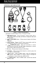


Table Of Contents

Scan Tool Controls
CONTROLS AND INDICATORS
3
9. DOWN button - When in MENU mode, scrolls DOWN through
the menu options. When LINKED to a vehicle, scrolls DOWN
through the current display screen to display any additional data.
10. GREEN LED - Indicates that all engine systems are running
normally (all Monitors on the vehicle are active and performing their
diagnostic testing, and no DTCs are present).
11. YELLOW LED - Indicates there is a possible problem. A “Pending”
DTC is present and/or some of the vehicle’s emission monitors have
not run their diagnostic testing.
12. RED LED - Indicates there is a problem in one or more of the
vehicle’s systems. The red LED is also used to show that DTC(s)
are present. DTCs are shown on the Scan Tool’s display. In this
case, the Malfunction Indicator (“Check Engine”) lamp on the
vehicle’s instrument panel will light steady on.
13. Display - Color LCD display shows menu and submenus, test
results, Scan Tool functions and Monitor status information. See
DISPLAY FUNCTIONS, following, for more details.
14. CABLE - Connects the Scan Tool to the vehicle’s Data Link
Connector (DLC).
Items 15 through 20 are available with purchase of the
optional OBD1 Adaptor Kit and OBD1 firmware upgrade.
15. CHRYSLER Connector Cable Adaptor - Installs on cable (item 14)
when connecting to a Chrysler OBD1 Data Link Connector.
16. FORD Connector Cable Adaptor - Installs on cable (item 14) when
connecting to a Ford OBD1 Data Link Connector.
17. GM Connector Cable Adaptor - Installs on cable (item 14) when
connecting to a GM OBD1 Data Link Connector.
18. HONDA Connector Cable Adaptor - Installs on cable (item 14)
when connecting to a Honda OBD1 Data Link Connector.
19. OBD II Cable - Connects the scan tool to the vehicle's Data Link
Connector (DLC) when retrieving codes from OBD II systems.
20. TOYOTA Connector Cable Adaptor - Installs on cable (item 14)
when connecting to a Toyota OBD1 Data Link Connector.