Table of Contents i ABOUT THE SCAN TOOL SAFETY FIRST! ....................................................................... CONTROLS AND INDICATORS .............................................. DISPLAY FUNCTIONS ............................................................ INITIAL ADJUSTMENTS .......................................................... 1 2 3 5 USING THE SCAN TOOL CODE RETRIEVAL PROCEDURE .......................................... THE SYSTEM MENU .........................................
About the Scan Tool SAFETY FIRST SAFETY FIRST! This manual describes common test procedures used by experienced service technicians. Many test procedures require precautions to avoid accidents that can result in personal injury, and/or damage to your vehicle or test equipment. Always read your vehicle's service manual and follow its safety precautions before and during any test or service procedure.
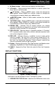
About the Scan Tool CONTROLS AND INDICATORS CONTROLS AND INDICATORS 13 14 10 12 7 11 1 4 2 5 3 6 9 8 Figure 1. Controls and Indicators See Figure 1 for the locations of items 1 through 14, below. 1. ERASE button - Erases Diagnostic Trouble Codes (DTCs) and "Freeze Frame" data from your vehicle's computer, and resets Monitor status. 2. SYSTEM MENU button – When pressed, displays the System Menu. 3.
About the Scan Tool DISPLAY FUNCTIONS 5. M (Menu) button – When pressed, displays the Main Menu. 6. LD button – When pressed while linked to a vehicle, places the Scan Tool in Live Data mode. 7. UP button – When in MENU mode, scrolls UP through the menu options. When LINKED to a vehicle, scrolls UP through the current display screen to display any additional data. 8. ENTER button - When in Menu mode, confirms the selected option or value. 9.
About the Scan Tool DISPLAY FUNCTIONS 2. Monitor icons - Indicate which Monitors are supported by the vehicle under test, and whether or not the associated Monitor has run its diagnostic testing (Monitor status). A solid green icon indicates the associated Monitor has completed its diagnostic testing. A flashing red icon indicates that the vehicle supports the associated Monitor, but the Monitor has not yet run its diagnostic testing. 3.
About the Scan Tool INITIAL ADJUSTMENTS 1 - Service should be scheduled and repairs made when convenient. This DTC typically has no immediate threat to essential system components in the short term. 2 - Repair immediately if drivability issues are present. Threat to essential system components if not repaired as soon as possible. 3 - Stop and repair vehicle immediately to prevent interrelated failures. Harmful and damaging to essential system components. 14.
Using the Scan Tool CODE RETRIEVAL PROCEDURE CODE RETRIEVAL PROCEDURE Retrieving and using Diagnostic Trouble Codes (DTCs) for troubleshooting vehicle operation is only one part of an overall diagnostic strategy. Never replace a part based only on the DTC definition. Each DTC has a set of testing procedures, instructions and flow charts that must be followed to confirm the location of the problem. Always refer to the vehicle's service manual for detailed testing instructions.
Using the Scan Tool CODE RETRIEVAL PROCEDURE 6. The Scan Tool automatically starts a check of the vehicle’s computer to determine which type of communication protocol it is using. When the Scan Tool identifies the computer’s communication protocol, a communication link is established. A PROTOCOL is a set of rules and procedures for regulating data transmission between computers, and between testing equipment and computers.
Using the Scan Tool CODE RETRIEVAL PROCEDURE To select a new vehicle, choose New Vehicle, then press ENTER . Proceed to step 9. 9. When New Vehicle is chosen from the Select Vehicle screen, the Select Make screen displays. Select the desired vehicle make, then press ENTER to continue. - The Vehicle Information screen displays. If the information shown is correct for the vehicle under test, select Yes, then press ENTER . Proceed to step 10.
Using the Scan Tool CODE RETRIEVAL PROCEDURE Yellow LED - Indicates one of the following conditions: A. A PENDING CODE IS PRESENT – If the yellow LED is illuminated, it may indicate a Pending code is present. Check the display for confirmation. A Pending code is confirmed by the presence of a numeric code and the word PENDING. B.
Using the Scan Tool THE SYSTEM MENU In OBD2 systems, when an emissions-related engine malfunction occurs that causes a DTC to set, a record or snapshot of engine conditions at the time that the malfunction occurred is also saved in the vehicle’s computer memory. The record saved is called Freeze Frame data.
Using the Scan Tool VIEWING OEM ENHANCED DTCs (except Ford/Mazda) VIEWING OEM ENHANCED DTCs (except Ford/Mazda) When (make) OEM Enhanced is chosen from the System Menu, the Scan Tool retrieves OEM enhanced DTCs from the vehicle’s computer. 1. A “One moment please” message displays while the Scan Tool retrieves the selected DTCs. If the Scan Tool fails to link to the vehicle’s computer, a “Communication Error” message shows. - Ensure your vehicle is OBD2 compliant.
Using the Scan Tool VIEWING OEM ENHANCED DTCs (Ford/Mazda only) To exit the enhanced mode, press SYSTEM MENU to return to the System Menu. Select Global OBD, then press ENTER to return to the Global OBD2 mode. VIEWING OEM ENHANCED DTCs (Ford/Mazda only) Mazda Enhanced DTCs are available for Mazda-branded Ford vehicles only. When Ford OEM Enhanced is chosen from the System Menu, the Ford OEM Enhanced menu displays.
Using the Scan Tool VIEWING ABS DTCs If the KOEO test was selected, and the vehicle’s engine is running, an advisory message shows. - Turn the ignition OFF then back ON and press ENTER to to return to the try again, or, press SYSTEM MENU System Menu. 4. If the KOER test was selected, an “instructional” message shows. Turn the steering wheel to the left, then release. Press and release the brake pedal. Cycle the overdrive switch (if equipped).
Using the Scan Tool VIEWING ABS DTCs If ABS functionality is not supported, an advisory message shows. Press SYSTEM MENU to return to the System Menu. If the Scan Tool fails to link to the vehicle’s computer, a "Communication Error" message shows. - Ensure your vehicle is OBD2 compliant. - Verify the connection at the DLC, and verify the ignition is ON. - Turn the ignition OFF, wait 5 seconds, then turn back ON to reset the computer. - Press LINK to continue.
Using the Scan Tool ERASING DIAGNOSTIC TROUBLE CODES (DTCs) ERASING DIAGNOSTIC TROUBLE CODES (DTCs) When the Scan Tool’s ERASE function is used to erase DTCs from the vehicle's on-board computer, "Freeze Frame" data and manufacturer-specific enhanced data are also erased. "Permanent" DTCs ARE NOT erased by the ERASE function. If you plan to take the vehicle to a Service Center for repair, DO NOT erase the codes from the vehicle's computer.
Using the Scan Tool ABOUT REPAIRSOLUTIONS 2® If the erase was successful, a confirmation message shows. The Scan Tool automatically relinks to the vehicle’s computer after 3 seconds. If the erase was not successful and ECU error code $22 is present, an advisory message displays. Start the engine and maintain vehicle speed at 0. Choose Erase DTCs to try again. If the erase was not successful, an advisory message shows indicating the erase request was sent to the vehicle’s computer.
Using the Scan Tool CONNECTING TO BLUETOOTH / WIFI If you have not yet established an account, you must register for a FREE RepairSolutions 2 account before proceeding. 3. Connect the Code Reader to a vehicle and establish a Bluetooth or WiFi connection with your Smart Device (refer to CONNECTING TO BLUETOOTH / WIFI, below). Be sure your Smart Device is connected to an available WiFi network. The RepairSolutions 2 app will store two WiFi configurations only. 4.
Live Data Mode VIEWING LIVE DATA The Scan Tool lets you view and/or record "real-time" Live Data. This information includes values (volts, rpm, temperature, speed etc.) and system status information (open loop, closed loop, fuel system status, etc.) generated by the various vehicle sensors, switches and actuators.
Live Data Mode CUSTOMIZING LIVE DATA (PIDs) 4. Only a limited amount of PID data can be displayed on the screen at one time. If additional PID data is available, a small arrow is shown on the display. Press UP and DOWN , as necessary, to view all available PID data. If communication with the vehicle is lost while viewing Live Data, an advisory message displays. 5. Press and release ENTER to view the currently selected PID in “graph” mode. Press and release ENTER again to return to the PID list.
Live Data Mode CUSTOMIZING LIVE DATA (PIDs) If Live Data is not supported by the vehicle under test, an to return advisory message displays. Press SYSTEM MENU to the System Menu. If custom Live Data was previously configured, the Select PIDs to Use screen displays. - To use the existing custom Live Data selections, select Use . Proceed to step 5. existing PIDs, then press ENTER - To configure new custom Live Data, select Select new PIDs, then press ENTER . The Custom Live Data menu displays.
Additional Functions SYSTEM TEST MENU In addition to retrieving Diagnostic Trouble Codes (DTCs), you can use the scan tool to perform additional diagnostic tests, to view diagnostic and vehicle information stored in your vehicle's on-board computer, and to configure the scan tool for your particular needs. Additional tests and related functions are accessed through the Main Menu.
Additional Functions SYSTEM TEST MENU O2 Sensor Test OBD2 regulations require that applicable vehicles monitor and test operation of the oxygen (O2) sensors to identify problems that can affect fuel efficiency and vehicle emissions. These tests are performed automatically when engine operating conditions are within predefined limits. Results of these tests are stored in the on-board computer's memory.
Additional Functions SYSTEM TEST MENU OBD Monitor Test The OBD Monitor Test function retrieves and displays test results for emission-related powertrain components and systems that are not continuously monitored. The tests available are determined by the vehicle manufacturer. The diagnostic tool does not perform the OBD monitor test, but retrieves results from the most recently performed tests from the on-board computer’s memory.
Additional Functions VIEWING VEHICLE INFORMATION The scan tool does not perform the leak test, but signals to vehicle's on-board computer to initiate the test. The vehicle manufacturer determines the criteria and method for stopping the test once it has been started. Refer to the vehicle's service repair manual to determine the procedures necessary to stop the test. 1. From the System Test menu, select EVAP Test, then press ENTER . 2. A "One moment please..." message displays. 3.
Additional Functions VIEWING VEHICLE INFORMATION 1. While linked to a vehicle, press M. The “Main Menu” displays. 2. Select Vehicle Information, then press ENTER The Vehicle Information menu displays. . 3. Select Vehicle ID, then press ENTER . The first time the Vehicle ID function is used, it may take several minutes to retrieve the information from the vehicle's computer. 4. When the retrieval process is completed, the vehicle ID information displays. 5.
Additional Functions BATTERY/ALTERNATOR TEST 2. Select Vehicle Information, then press the ENTER The Vehicle displays. Information button. menu . 3. Select IPT, then press ENTER 4. When the retrieval process is completed, the In-use Performance Tracking statistics for the vehicle under test display. If In-use Performance Tracking is not available for your vehicle, an advisory message shows on the diagnostic tool’s display. Press M to return to the Main Menu. 5.
Additional Functions BATTERY/ALTERNATOR TEST If the engine is running, an advisory message shows. Turn the engine off, then turn the ignition on. DO NOT start the engine. Press ENTER to continue. An “instructional” message shows. 6. Turn the vehicle’s headlights on, then press ENTER to continue. A “countdown” message shows while the battery check is in process. If battery voltage is less than 12.1 volts, an advisory message shows. Press M to return to the Main Menu.
Additional Functions VIEWING THE FIRMWARE VERSION - THE TOOL LIBRARY 4. Start and warm the engine to normal operating temperature. Turn on the headlights. Press ENTER to continue. An “instructional” message shows. 5. Press the accelerator pedal to raise engine speed to 2000 RPM, and maintain the engine speed. When engine speed is within the required range, the alternator test begins. A progress screen shows. When the “countdown” timer expires, an “instructional” message shows. 6.
Additional Functions THE TOOL LIBRARY Tool Icons – Shows the full names for the I/M MONITOR STATUS icons and descriptions of informational icons shown on the scan tool’s display. DTC Library – Provides access to a library of OBD2 DTC definitions. LED Definitions – Provides descriptions of the meaning of the scan tool SYSTEM STATUS LEDs. 1. While linked to the vehicle, press M. 2. The Main Menu displays. Select Tool .. ENTER Library, then press The Tool Library menu displays.
Additional Functions ADJUSTMENTS AND SETTINGS 4. Use the UP and DOWN buttons, as necessary, to scroll to the desired DTC type (P=Powertrain, U=Network, B=Body, C=Chassis), then press the DTC button. The selected character displays solid, and the next character is highlighted. 5. Select the remaining digits in the DTC in the same way. When you have selected all the DTC digits, press to continue. ENTER 6.
Additional Functions ADJUSTMENTS AND SETTINGS Footer Messages: Turns the navigational “footers” at the bottom of most display screens “on” and “off.” Hotkey Legend: Shows functional descriptions for the diagnostic tool’s hotkeys. Language Selection: Sets the display language for the Scan Tool to English, French or Spanish. Unit of Measurement: Sets the Unit of Measurement for the Scan Tool’s display to USA or Metric. To enter the Tool Settings Menu: 1.
Additional Functions ADJUSTMENTS AND SETTINGS Enabling/Disabling Navigational Footers 1. Select Footer Messages in the Tool Settings menu, then press ENTER . The Footer Messages screen displays. 2. Select On of Off as desired, then press to save your changes. ENTER To return to the Tool Settings menu without making changes, press M. Viewing the Hotkey Legend 1. Select Hotkey Legend in the Tool Settings menu, then press ENTER . The Hotkey Legends screen displays.
Warranty and Servicing LIMITED ONE YEAR WARRANTY The Manufacturer warrants to the original purchaser that this unit is free of defects in materials and workmanship under normal use and maintenance for a period of one (1) year from the date of original purchase. If the unit fails within the one (1) year period, it will be repaired or replaced, at the Manufacturer’s option, at no charge, when returned prepaid to the Service Center with Proof of Purchase. The sales receipt may be used for this purpose.