Table of Contents i SAFETY PRECAUTIONS SAFETY FIRST! ....................................................................... 1 SCAN TOOL CONTROLS CONTROLS AND INDICATORS ............................................. DISPLAY FUNCTIONS ............................................................ 2 3 USING THE SCAN TOOL CODE RETRIEVAL PROCEDURE .......................................... THE SYSTEM MENU................................................................
Safety Precautions SAFETY FIRST! SAFETY FIRST! This manual describes common test procedures used by experienced service technicians. Many test procedures require precautions to avoid accidents that can result in personal injury, and/or damage to your vehicle or test equipment. Always read your vehicle's service manual and follow its safety precautions before and during any test or service procedure.
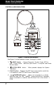
Scan Tool Controls CONTROLS AND INDICATORS CONTROLS AND INDICATORS 14 13 10 12 7 11 1 4 2 5 3 6 9 8 Figure 1. Controls and Indicators See Figure 1 for the locations of items 1 through 14, below. 1. ERASE button - Erases Diagnostic Trouble Codes (DTCs), and “Freeze Frame” data from your vehicle’s computer, and resets Monitor status. 2. SYSTEM MENU Test Menu. button – When pressed, displays the System 3.
Scan Tool Controls DISPLAY FUNCTIONS 5. M button – When pressed, displays the Main Menu. 6. LD button – When pressed while linked to a vehicle, places the Scan Tool in Live Data mode. 7. UP button – When in MENU mode, scrolls UP through the menu options. When LINKED to a vehicle, scrolls UP through the current display screen to display any additional data. 8. ENTER button - When in MENU mode, confirms the selected option or value. 9.
Scan Tool Controls DISPLAY FUNCTIONS 1. I/M MONITOR STATUS field - Identifies the I/M Monitor status area. 2. Monitor icons - Indicate which Monitors are supported by the vehicle under test, and whether or not the associated Monitor has run its diagnostic testing (Monitor status). A solid green icon indicates the associated Monitor has completed its diagnostic testing. A flashing red icon indicates that the vehicle supports the associated Monitor, but the Monitor has not yet run its diagnostic testing. 3.
Scan Tool Controls INITIAL ADJUSTMENTS 13. Severity - Indicates the level of severity for the priority code (code number “1”), as follows: 1 - Service should be scheduled and repairs made when convenient. This DTC typically has no immediate threat to essential system components in the short term. 2 - Repair immediately if drivability issues are present. Threat to essential system components if not repaired as soon as possible. 3 - Stop and repair vehicle immediately to prevent interrelated failures.
Using the Scan Tool CODE RETRIEVAL PROCEDURE CODE RETRIEVAL PROCEDURE Retrieving and using Diagnostic Trouble Codes (DTCs) for troubleshooting vehicle operation is only one part of an overall diagnostic strategy. Never replace a part based only on the DTC definition. Each DTC has a set of testing procedures, instructions and flow charts that must be followed to confirm the location of the problem. Always refer to the vehicle's service manual for detailed testing instructions.
Using the Scan Tool CODE RETRIEVAL PROCEDURE 6. The Scan Tool automatically starts a check of the vehicle’s computer to determine which type of communication protocol it is using. When the Scan Tool identifies the computer’s communication protocol, a communication link is established. A PROTOCOL is a set of rules and procedures for regulating data transmission between computers, and between testing equipment and computers.
Using the Scan Tool CODE RETRIEVAL PROCEDURE To select a new vehicle, select New Vehicle, then press ENTER . Proceed to step 9. 9. When New Vehicle is chosen from the Select Vehicle screen, the Select Year screen displays. Select the desired vehicle model year, then press ENTER to continue. - Select the desired vehicle make, then press ENTER to continue. - The Select Model screen displays. Select the desired vehicle model, then press ENTER to continue. - The Select Make screen displays.
Using the Scan Tool CODE RETRIEVAL PROCEDURE 11. Refer to DISPLAY FUNCTIONS on page 3 for a description of display elements. In the case of long code definitions, a small arrow is shown in the upper/lower right-hand corner of the Scan Tool display area to indicate the presence of additional information. If a definition for the currently displayed code is not available, an advisory message shows. 12.
Using the Scan Tool CODE RETRIEVAL PROCEDURE Red LED – Indicates there is a problem with one or more of the vehicle’s systems. The red LED is also used to indicate that DTC(s) are present. In this case, the Malfunction Indicator (Check Engine) lamp on the vehicle’s instrument panel will be illuminated. DTC’s that start with “P0”, “P2” and some “P3” are considered Generic (Universal). All Generic DTC definitions are the same on all OBD2 equipped vehicles.
Using the Scan Tool THE SYSTEM MENU - VIEWING OEM ENHANCED DTCs (except Ford/Mazda) THE SYSTEM MENU The System Menu provides the ability to retrieve “enhanced” DTCs, AntiLock Brake System (ABS) and Supplemental Restraint System (SRS) DTCs for most BMW, Chrysler/Jeep, Ford/Mazda, GM/Isuzu, Honda/Acura, Hyundai, Mercedes Benz, Nissan, Toyota/Lexus, Volkswagen and Volvo vehicles. The types of enhanced data available depends on the vehicle make. You can also return to the Global OBD2 mode.
Using the Scan Tool VIEWING OEM ENHANCED DTCs (Ford/Mazda only) 2. Refer to DISPLAY FUNCTIONS on page 2 for a description of LCD display elements. If the definition for the currently displayed code is not available, an advisory message shows. I/M MONITOR STATUS icons are not displayed when viewing enhanced DTCs. In the case of long code definitions, a small arrow is shown in the upper/lower right-hand corner of the code display area to indicate the presence of additional information.
Using the Scan Tool VIEWING OEM ENHANCED DTCs (Ford/Mazda only) Turn the ignition OFF, then back ON. Press ENTER Proceed to step 3. . 3. A “One moment please” message displays while the test is in progress. If the Scan Tool fails to link to the vehicle’s computer, a “Communication Error” message shows. - Ensure your vehicle is OBD2 compliant. - Verify the connection at the DLC, and verify the ignition is ON. - Turn the ignition OFF, wait 5 seconds, then back ON to reset the computer.
Using the Scan Tool VIEWING ABS DTCs If no codes are present, a “System Pass” message is displays. Press any Hotkey. 6. If more than one code was retrieved press DTC/FF to display additional codes one at a time. 7. When the last retrieved DTC has been displayed and DTC/FF is pressed, the Scan Tool returns to the “Priority” Code. To view additional enhanced DTCs, repeat steps 1 through 5, above. To exit the enhanced mode, press SYSTEM MENU to return to the System Menu.
Using the Scan Tool VIEWING SRS DTCs If the definition for the currently displayed code is not available, an advisory message shows. I/M MONITOR STATUS icons are not displayed when viewing ABS DTCs. In the case of long code definitions, a small arrow is shown in the upper/lower right-hand corner of the code display area to indicate the presence of additional information. If no codes are present, the message "No ABS DTC’s are presently stored in the vehicle’s computer" shows.
Using the Scan Tool NETWORK TEST If the Scan Tool cannot link to the vehicle’s computer after three attempts, the message “Contact Technical Support” displays. - Press SYSTEM MENU to return to the System Menu. - Turn the ignition off, and disconnect the Scan Tool. - Contact Technical Support for assistance. 2. Refer to DISPLAY FUNCTIONS on page 2 for a description of LCD display elements. If the definition for the currently displayed code is not available, an advisory message shows.
Using the Scan Tool NETWORK TEST DTCs recorded for each available module. 2. Select the module for which you wish to view DTCs, then press ENTER . A “One moment please” message displays while the requested DTCs are retrieved. If the Scan Tool fails to link to the selected module, a “Communication Error” message shows. - Ensure your vehicle is OBD2 compliant. - Verify the connection at the DLC, and verify the ignition is ON. - Turn the ignition OFF, wait 5 seconds, then back ON to reset the computer.
Using the Scan Tool NETWORK TEST To scan a selected module: 1. Choose Select Modules from the System Menu, then press ENTER . If the Select Group screen displays, select the group (Drive, Chassis, Body, etc.) containing the module you wish to scan, then press ENTER . Proceed to step 2. If the Select Group screen does not display, proceed to step 2. 2. The Available Systems screen displays. Select the desired module, then press ENTER .
Using the Scan Tool ERASING DIAGNOSTIC TROUBLE CODES (DTCs) 5. If more than one code was retrieved press DTC/FF to display additional codes one at a time. Whenever the Scroll function is used, the Scan Tool’s communication link with the vehicle’s computer disconnects. To re-establish communication, press POWER/LINK again. 6. When the last retrieved DTC has been displayed and DTC/FF is pressed, the Scan Tool returns to the first code.
Using the Scan Tool ABOUT REPAIRSOLUTIONS® If you do not want to proceed, select No, then press ENTER to cancel the erase procedure. 4. If you chose to erase DTCs, a “One moment please…” message displays while the erase function is in progress. If the vehicle’s engine is running, an advisory message shows. Turn the engine OFF, then turn the ignition back to ON. DO NOT start the engine. Press ENTER to continue. If the erase was successful, a confirmation message shows.
Using the Scan Tool CONNECTING TO BLUETOOTH / WIFI Video Tutorials – Watch repair video tutorials for valuable repair tips. Technical Service Bulletins – Research known problems reported by vehicle manufacturers. Safety Recalls – Research known safety concerns applicable to a vehicle. And much more. Please visit www.innova.com for additional information. Hardware Requirements: Innova Scan Tool with Bluetooth/WiFi Android or iOS Smart Device Accessing RepairSolutions 2® 1.
Using the Scan Tool CONNECTING TO BLUETOOTH / WIFI You can automatically connect to the network your Smart Device is currently connected to, or you can manually connect to another available network. Note that only 2.4GHz networks are supported. If you do not wish to connect to a WiFi network at this time, tap SKIP. 4. When WiFi pairing is complete, a confirmation screen displays. Click Continue to view the “Setup Complete” message, then click Continue to enter RepairSolutions2.
Live Data Mode VIEWING LIVE DATA The Scan Tool lets you view and/or "capture" (record) "real-time" Live Data. This information includes values (volts, rpm, temperature, speed etc.) and system status information (open loop, closed loop, fuel system status, etc.) generated by the various vehicle sensors, switches and actuators.
Live Data Mode CUSTOMIZING LIVE DATA (PIDs) If communication with the vehicle is lost while viewing Live Data, a Communication Lost" message shows on the Scan Tool's display. 5. Press and release ENTER to view the currently selected PID in “graph” mode. Press and release ENTER again to return to the PID list. You can display a maximum of two PIDs in "graph" mode at any given time. With two PIDs shown in "graph" mode, press and hold LD to superimpose one graph on the other.
Live Data Mode RECORDING (CAPTURING) LIVE DATA If Live Data is not supported by the vehicle under test, an advisory message displays. Press SYSTEM MENU to return to the System Menu. If custom Live Data was previously configured, the Select PIDs to Use screen displays. - To use the existing custom Live data selections, select Use existing PIDs, then press ENTER . Proceed to step 5. - To configure new custom Live Data, select Select new PIDs, then press ENTER . The Custom Live Data menu displays.
Live Data Mode RECORDING (CAPTURING) LIVE DATA Record by DTC Trigger This function automatically records Live Data information when a DTC sets and saves it in the Scan Tool’s memory. The recorded data can be a valuable troubleshooting aid, particularly if you are experiencing a fault that is causing a DTC to set. The Scan Tool can record approximately 100 frames of Live Data. 1.
Live Data Mode RECORDING (CAPTURING) LIVE DATA - To retry the erase process, verify that the Scan Tool is properly connected to the vehicle’s DLC and that the ignition is on. Select Erase, then press ENTER . - To exit the record function, select Back, then press ENTER to return to the Record Live Data menu. The Record Live Data screen displays. 6. Put the engine in the operating condition that causes the DTC to set.
Live Data Mode LIVE DATA PLAYBACK The Select PIDs to Record screen displays. 4. Press UP and DOWN to scroll through the available PIDs. When a PID you wish to record is highlighted, press (a “checkmark” shows to ENTER confirm your selection). Repeat until only the PIDs you want to record have all been selected. To deselect a PID, highlight the PID, then press ENTER checkmark is removed. . The To record all PIDs, select Record All PIDs, the press LD to continue. 5.
Live Data Mode LIVE DATA PLAYBACK When you select Yes from the Record Live Data confirmation screen, the Scan Tool enters the "Live Data Playback" mode, and the Playback Live Data menu displays. 3. Select Continuous Playback or Frame by Frame, as desired, then press ENTER . The display shows the recorded Live Data, beginning with the "trigger" frame. Only a limited amount of PID data can be displayed on the screen at one time.
Additional Tests SYSTEM TEST MENU In addition to retrieving Diagnostic Trouble Codes (DTCs), you can use the Scan Tool to perform additional diagnostic tests, to view diagnostic and vehicle information stored in your vehicle's on-board computer, and to configure the Scan Tool for your particular needs. Additional tests and related functions are accessed through the Main Menu.
Additional Tests SYSTEM TEST MENU The Main Menu displays. 2. Select System . ENTER Tests, then press The System Test menu displays. If System Tests is not shown on the Main Menu, the System Tests functions are not available for your vehicle. O2 Sensor Test OBD2 regulations require that applicable vehicles monitor and test operation of the oxygen (O2) sensors to identify problems that can affect fuel efficiency and vehicle emissions.
Additional Tests SYSTEM TEST MENU 6. When you have finished viewing test data for all desired sensors, select Back, then press ENTER to return to the System Test menu; or, press M to return to the Main Menu. OBD Monitor Test The OBD Monitor Test function retrieves and displays test results for emission-related powertrain components and systems that are not continuously monitored. The tests available are determined by the vehicle manufacturer.
Additional Tests RESETTING THE OIL MAINTENANCE LIGHT EVAP Test The EVAP Test function lets you initiate a leak test for the vehicle's EVAP system. The Scan Tool does not perform the leak test, but signals to vehicle's on-board computer to initiate the test. The vehicle manufacturer determines the criteria and method for stopping the test once it has been started. Refer to the vehicle's service repair manual to determine the procedures necessary to stop the test. 1.
Additional Tests BATTERY RESET If the Scan Tool cannot reset the Oil Maintenance Light, an “instructional” dialog displays, showing the manual procedures for resetting the indicator light. When finished viewing the instructions, press M to return to the Main Menu. 4. The Reset Oil Maintenance Indicator screen displays. If you do not wish to proceed with the reset process, select No, then press ENTER to return to the System Menu.
Additional Tests BATTERY RESET If battery reset procedures are not available for your vehicle, an advisory message shows. Press M to return to the Main Menu. 4. Select the procedure you wish to view, . then press ENTER The selected procedure displays. 5. When you have finished viewing the retrieved information, press M to return to the Main Menu. Repeat steps 2 through 4 to view additional procedures.
Additional Tests PERFORMING A SERVICE CHECK - BATTERY/ALTERNATOR TEST PERFORMING A SERVICE CHECK The Service Check function lets you check the current oil level and oil life. 1. While linked to the vehicle, press M. The Main Menu displays. 2. Select Service Check, then press ENTER . The Service Check screen displays. The screen shows the current Engine Oil Level and Oil Life Remaining. 3. When you have finished viewing the information, press M to return to the Main Menu.
Additional Tests BATTERY/ALTERNATOR TEST Turn the ignition on. DO NOT start the engine. 5. Press ENTER to begin the battery check. If the engine is running, an advisory message shows. Turn the engine off, then turn the ignition on. DO NOT start the engine. Press ENTER to continue. An “instructional” message shows. 6. Turn the vehicle’s headlights on, the press ENTER to continue. A “countdown” message shows while the battery check is in process. If battery voltage is less than 12.
Additional Tests BATTERY/ALTERNATOR TEST 3. Select Alternator Test, then press ENTER . An “instructional” message shows. 4. Start and warm the engine to normal operating temperature. Turn on to continue. the headlights. Press ENTER An “instructional” message shows. 5. Press the accelerator pedal to raise engine speed to 2000 RPM, and maintain the engine speed. When engine speed is within the required range, the alternator test begins. A progress screen shows.
Additional Tests VIEWING TRIP CYCLE PROCEDURES If the vehicle supports battery Live Data, the Battery Live Data screen displays. The screen shows the state of charge, battery pack voltage and sum of cell voltages for the battery pack. If the vehicle supports battery cell display, a graphic display of the current state of charge for all cells in the battery pack displays. 4. When you have finished viewing the retrieved information, press M to return to the Main Menu.
Additional Tests USING THE DLC LOCATOR 5. Select the Monitor for which you wish to view Drive Cycle Procedures, then press ENTER . A “One moment please…” message displays while the Scan Tool retrieves the requested Drive Cycle Procedure. The Drive Cycle Procedures screen for the Monitor displays when the procedure has been retrieved. If a Drive Cycle Procedure for the selected Monitor is not available, an advisory message shows. Select Back, then press ENTER to return to the Main Menu. 6.
Additional Tests VIEWING VEHICLE INFORMATION VIEWING VEHICLE INFORMATION The Vehicle Information function offers three options for retrieving reference information for the vehicle under test; Vehicle ID, Available Modules and IPT (In-Use Performance Tracking). Retrieving Vehicle ID Information The Vehicle ID function is applicable to model year 2000 and newer OBD2-compliant vehicles.
Additional Tests THE TOOL LIBRARY 2. Select Vehicle Information, then press ENTER . The Vehicle displays. Information menu 3. Select Available Modules, then press ENTER . 4. When the retrieval process is completed, a complete list of modules supported by the vehicle under test displays. 5. When you have finished viewing the list of available modules, press M to return to the Main Menu.
Additional Tests THE TOOL LIBRARY The Firmware Version screen displays for four seconds. The screen shows the Scan Tool’s current firmware version, bootloader version and database version. 2. The display returns to the Main Menu. THE TOOL LIBRARY The Tool Library contains valuable reference information for the Scan Tool.
Additional Tests THE TOOL LIBRARY Using the DTC Library 1. From the Tool Library menu, select . DTC Library, then press ENTER The Select Library screen displays. 2. Select OBD2 . ENTER Library, then press The Select Manufacturer screen displays. 3. Select the desired vehicle manufacturer, then press ENTER . The Enter DTC screen displays. The screen shows the code “P0001,” with the “P” highlighted. 4.
Additional Tests ADJUSTMENTS AND SETTINGS The screen provides a description of the meanings of the green, yellow and red SYSTEM STATUS LEDs. 2. When you have finished viewing the LED meanings, press M to return to the Main Menu. ADJUSTMENTS AND SETTINGS The Scan Tool lets you make several adjustments and settings to configure the Scan Tool to your particular needs. The following adjustments and settings are available: Adjust Brightness: Adjusts the brightness of the display screen.
Additional Tests ADJUSTMENTS AND SETTINGS Enabling/Disabling the Audible Tone 1. Select Audible Tone in the Tool Settings menu, then press ENTER . The Audible Tone screen displays. 2. Select On or Off as desired, then press ENTER to save your changes. To return to the Tool Settings menu without making changes, press M. Enabling/Disabling Navigational Footers 1. Select Footer Messages in the Tool Settings menu, then press ENTER . The Footer displays. Messages screen 2.
Additional Tests ADJUSTMENTS AND SETTINGS Setting the Unit of Measurement 1. Select Unit of Measurement in the Tool Settings menu, then press ENTER . The Unit of Measurement screen displays. 2. Select the desired unit of measurement, then choose Save to save your changes. To return to the Tool Settings menu without making changes, press M. Exiting the MENU Mode Press M to return to the Main Menu.
Notes 48
Warranty and Servicing LIMITED ONE YEAR WARRANTY The Manufacturer warrants to the original purchaser that this unit is free of defects in materials and workmanship under normal use and maintenance for a period of one (1) year from the date of original purchase. If the unit fails within the one (1) year period, it will be repaired or replaced, at the Manufacturer’s option, at no charge, when returned prepaid to the Service Center with Proof of Purchase. The sales receipt may be used for this purpose.