DL-32 Multi-sensor Universal Data Logger User Manual DL32_Manual_1.3.
1. 2. Overview ............................................................................................................................... 4 The Innovate Log-Chain concept ......................................................................................... 4 2.1 Log-Chain of 5 channels consisting of DL-32 alone. ........................................................ 5 2.2 7-channel Log-Chain example with 2 AFR channels........................................................ 5 2.
13.7 Input 5 Configuration ................................................................................................... 27 14. Kit Contents ........................................................................................................................ 28 Appendix A: Limited Warranty ...................................................................................................... 29 Revision History..........................................................................................
1. Overview The DL-32 is a data logger with 5 general purpose inputs. It can record these inputs on a SD memory card. In addition to its own native 5 inputs the DL-32 can record data from other Innovate MTS (Modular Tuning System) devices up to a total of 32 recorded channels. A 32-channel recording requires a memory space of 1Mbyte in the SD card every 17 minutes. A 16Mbyte card therefore can record 272 minutes or about 4-1/2 hours.
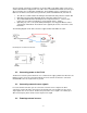
pass it on. An example of a case where the command is executed but not passed on is the startstop record command. The first upstream device capable of logging internally will execute the command, but not pass it on. As said before, the first device is special because it is the synchronization source for the entire chain. By plugging its IN-port with the supplied terminator connector, a device can detect that requirement when it powers up.
Devices attached to the LM-1’s analog input count as being part of the LM-1’s 6 channels. They don’t count extra. XD-16’s do not contribute any channels, so you can add as many as needed. 3. Connecting the DL-32 The DL-32 looks like this: 3.
As part of the DL-32 package you will have received a LED, a push-button switch, and a stereo 3.5mm cable with three stripped ends. The cable can be extended with shielded stereo wire up to 30 feet. This kit is the record button and indicator. The installation of this is required if you do NOT have an XD-16 connected in the log-chain after (chained to SERIAL OUT) of the DL-32. 1. 2. 3. 4. The drill size recommended for mounting the included momentary switch is a 25/64” drill.
At the connection marked 5V you can connect external sensors. External sensors don’t HAVE to be powered by the DL-32. The 5V output is a convenience for external sensors when no 5V supply is available. The 5V supply can power sensors with a total power consumption of up to 300mA. 3.5 Connecting an RPM signal For RPM measurement you can either connect a tach signal to the CH1+ input or plug an inductive clamp into the 3.5 mm stereo socket marked RPM. See chapter 6 for RPM measurement details. 3.
Constantan wire of the probe. This extra junction will cause a large error in the temperature readings. Most Thermocouple probes are of the “grounded junction” type. This means that the “hot junction” is also connected to the probe’s body. As this body is connected for example to the exhaust manifold, the sensor wires are essentially grounded through that.
To insert an SD card into the DL-32, push it into the SD card slot until it “clicks” in. To remove the SD card, push on it to “unclick” it. It will pop out. To read an SD card with a computer, you will need an SD card reader. Those are available in most computer stores. They typically connect to a USB port on your computer. A SD card inserted into an SD card reader on your computer will appear on your computer as a removable mass storage device. To find it, open on your computer the “my Computer Icon”.
Alternatively you can start/stop recording with an XD-1/XD-16 chained to the serial OUT port of the DL-32. Pushbutton and Indicator LED operation Press the push button briefly to start or stop a recording. When the DL-32 is NOT recording, the LED will be steadily lit. When the button is pressed, the LED will go out. When actively recording, it will blink twice a second.
A log window will be opened: Sessions are named “Session 1”, “Session 2”, etc. If a DL-32 session is too long for LogWorks (longer than 1-1/2 hours), it is broken up and a letter is used (ex. “Session 2a”, “Session 2b”, etc.). 4.7 Deleting log files from the SD-card The SD-card must be inserted into an SD card reader connected to your computer. The SD-card looks to your computer just like any other mass-storage device like a CD, Floppy or hard-drive.
on a flat, horizontal, surface and press and hold all three buttons together until the display shows the letter ‘A’: After this, re-try the above calibration procedure. You can now mount the DL-32. 6. Setting up the input channels The DL-32 can be programmed directly through the setup buttons on the DL-32. Alternatively, the LM Programmer software version 3.09 (or later) allows you to program the DL-32 via the LM Programmer software.
Input 4 Functions Function Indicator Functionality 1 2 3 4 F d = MAP (1 bar) (0..101.3 kPa) MAP (3 bar) (0..304.1 kPa) Vacuum (0..30 inHg Vacc) Vacuum/Boostt (-14.7PSI… 29.4 PSI) Frequency (straight frequency, Speed sensor, Custom RPM range Duty Cycle External 0..5V sensors Input 5 Functions Function Indicator Functionality 1 2 3 F d = Acceleration (+- 2g) Acceleration (+- 1g) Acceleration (+- 0.
With pulsed signals the measured information is contained either in the frequency of a pulse train or the duty cycle of a pulse trains. Examples for frequency type signals are RPM, speed and some MAF sensors. Duty cycle signal examples are contact dwell of a contact type ignition system or the duty cycle of fuel injectors. For all pulse type signals the actual voltage of a pulse must rise (ON phase) above 2.5V, the pulse must fall (OFF phase) below 2.5V to be measurable by the DL-32. 7. RPM measurement 7.
7.1.2 Two-Stroke Engines On a 2-stroke engine there is a spark for every crank rotation, so the spark frequency doubles compared to a 4-stroke.Very few multi-cylinder 2-strokes have distributors. For those that do, the number of ignition pulses per crank rotation is equal to the number of cylinders. Most two-stroke engines have one coil for every cylinder. The coil fires once for every crank revolution, the same as on a 4-Stroke Waste Spark system. 7.1.
- Determine the number of ignition pulses per crank rotation. Refer to Table 2 or 3 for guidance. - Press the ‘Channel’ button until it shows channel 1. - Press the ‘Function’ button until it shows 1 or 2. Use 1 if your engine’s redline is below 10000 RPM. Otherwise use 2. - Press the ‘Calibrate’ button until the selected Cyl.
The inductive clamp measures the magnetic field created around a spark plug wire when spark current flows. If a metallic shield covers the spark plug wire, the inductive clamp may not work because the shield would short out the magnetic field. Like all inductive clamp rpm pickup devices, some ignition systems like Capacitive Discharge Ignition (CDI) or multi-spark ignition systems may not work properly with the inductive clamp pickup because the pulses created may be too short in duration.
8. Measuring Pressures The DL-32 has a built in MAP sensor. To use it, connect a small ¼” hose between a vacuum/boost connection AFTER the throttle body and the DL-32 MAP input port. It should be connected after the throttle body because the lowest pressure that can be measured before the throttle body is atmospheric pressure (discounting some pressure losses from the intake tract before the throttle body). MAP stands for Manifold Absolute Pressure.
can be up to 29.4 PSI above atmospheric pressure. Vacuum is typically measured here as negative PSI. But you can set up any metric you want with LogWorks 2. 9. Measuring Frequencies, custom RPM, or speed The DL-32 has the capability to measure frequencies on channels 3, 4, and 5. It converts a frequency signal (pulses per second) into a voltage (0..5V) to be logged in the LM-1 or a number between 0 and 1023 to be logged directly by LogWorks.
11. Measuring external 5V sensors Each of the 5 channels on the DL-32 can be configured to accept input from an external 0..5V sensor. Hookup is very straight forward, with ground going to the ‘-‘ input for the channel and the positive sensor signal going to the ‘+’ input for the channel. Raw sensor data can be converted into meaningful units and values using the input configuration features of LogWorks on a PC. 11.1 Calibrating external 5V inputs DL-32 external inputs are factory calibrated.
• Connect the ground from the external sensor supply to the GND connection on the DL-32 • Connect the +5V from the external sensor supply to the ‘+’ input of the channel to be calibrated • Press the Channel button until the channel number to be calibrated is displayed • Press and hold the Calibrate button while the channel number is still displayed The DL-32 will either display a lower case ‘c’ to indicate the Calibration has occurred for the selected channel or an upper case ‘E’ to indicate that th
• Press the Channel button until the channel number to be calibrated is displayed • Press and hold the Calibrate button while the channel number is still displayed The DL-32 will either display a lower case ‘d’ to indicate the defaults have been restored for the selected channel or an upper case ‘E’ to indicate that the restoration could not occur. Normally an E indicates that more than .1V is being detected on the selected input. 12.
The LM Programmer software then shows in its first page the type and version number of the firmware of the device. 13.1 Changing the device name If multiple DL-32’s are used in a Log-Chain, each MUST be given a unique name so that LogWorks can identify each DL-32. Just enter a name in the edit box in this page. 13.2 Updating the firmware Click on the ‘Update Firmware’ button. You will be presented with a file dialog box that allows you to select a firmware file.
The drop-down list at the top of the window allows you to select the different functionality for that input. If RPM is selected, the area below the functionality selection shows as above. Select the cylinder count in the appropriate drop-down list. 13.4 Input 2 Configuration Function 1 and 2 of Input 2 use the TK+ and TK- inputs. The CH2+ and CH2- inputs are used ONLY of this input is set for “external 0..
13.5.2 Measuring Frequency The center section of the window changes to this: You can enter any frequency between 10 Hz and 15000 Hz as full scale frequency. DL-32 measures the frequency with a resolution of 0.1 % of the full scale frequency specified. So in LogWorks 0 Hz is always 0 Volt, and the full-scale frequency is equivalent to 5 Volt. This functionality is also available for Inputs 4 and 5. 13.5.3 Measuring Speed Select the Speed sensing function in the topmost drop-down list.
Select if you use a drive-shaft sensor or a wheel sensor. Enter the pulses per rotation created by the sensor either as driveshaft rotation or wheel rotation. You also need to enter the wheel diameter, and in case of a drive-shaft sensor, the final drive (differential) ratio. The LM-Programmer will calculate the pulses per mile (km) for you. This functionality is also available for Inputs 4 and 5. 13.6 Input 4 configuration Function 1,2,3 and 4 on this input are used for pressure measurement.
14.Kit Contents DL-32 Kit P/N: 3782 Hardware Kit P/N: 3786 Record Cable P/N: 3730 SD Memory Card P/N: 3787 Push Button/ LED P/N: 3773 Serial Cable P/N: 3746 DL-32 Software CD Quick Start Guide Terminator Plug P/N: 3750 - 28 - 2.5 to 2.
Appendix A: Limited Warranty LIMITED WARRANTY Innovate stands behind the quality of its products. Innovate makes the following warranty to purchasers of its products: All new Innovate products carry a six-month warranty from the date of purchase. If proof of purchase cannot be provided, warranty will be determined by date of manufacture.
Revision History 1.0 - 3/31/06 Initial Release 1.1 – 9/14/07 Added Kit Contents 1.2 – 2/20/08 Added terminator plug information 1.