
User's Manual


Installation Manual UL Addendum (UL 294, BP9480) iii
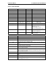
FOR UL LISTED SYSTEMS:
MODEL VOLTAGE, V FREQUENCY CURRENT
ESI, ESR, ES 120 V 50-60 HZ 1 A
ESRI, ESRR 12 DC 50 mA
TW 24 DC (RMS) 150 mA
FPI, FPIB 12 DC 120 mA
SAP 12 DC 300 mA
GDP 12 DC 500 mA
ED 12 DC 100 mA
ADD 12 DC 100 mA
PS51, PS68 PRI – 120 V
SEC – 12 V
PRI – 60 HZ
SEC - DC
PS51 = 5.1 A
PS68 = 6.8 A
MX, MXB 12 DC 500 mA
LT, SB, BR, CB 3.0 DC Standby off = 1.5 uA
Standby on = 5 uA
Transmit (BR) = 1.6 mA
Transmit activated (all) = 3 mA
TAD, PTAD 9 DC NSC = 20 mA,
Transmit = (2s)80 mA
CL-8A 12 DC NSC = 15 mA,
Alarm = 55 mA
MODEL OPERATION
ESI, ESR Controller coordinates and controls all of the devices and functions.
ES Controller PCB
ESRI, ESRR
Receiver picks up signal from an activated Tag and relays it to the
Controller (ESI) and the Multiplexer (MX).
TW
Transmit wand antenna generates a Tag-activating signal near a monitored
zone.
FPI, FPIB
Fire Panel Interface ensures that in the event of a fire alarm, the Lock and
Elevator Deactivator will disengage.
SAP
Staff Alert Panel notifies staff when an activated Tag enters a monitored
zone via a piezo and LEDs.
GDP
Graphic Display Panel provides staff with a visual representation of the floor
being monitored and notifies staff when an activated Tag enters a monitored
zone via a piezo and LEDs.
ED Elevator Deactivator prevents monitored residents from using the elevator.
ADD
Automatic Door Deactivator prevents monitored residents from using the
door.
PS51, PS68 Power Supply
MX, MXB
Multiplexer relay event information from the Controller to Graphic Display
Panels (GDP) and to the PC.