
User's Manual

Installation Manual Appendix B-7
NOTES:
A Door Ajar condition occurs after a door
has been open for a period of time (set by
potentiometer R97 and jumper JP11).
To override this delay and make this alarm
occur the moment the door is opened,
connect a +12V signal to P6-pin 2 (Door
Timer Override) of the Controller.
This LED will continue to illuminate steady
Red until the Door Ajar condition is
corrected (close the door and enter an
authorized code into the Keypad).
LED9
(Loiter Indicator; Steady Yellow)
This LED indicates a Loiter condition.
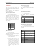
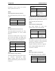
Table B.15
LED9 status Signals
Off No Tag(s) present
On, steady Yellow Loiter condition
NOTES:
A Loiter condition is when a Tag lingers in
the Tx Activation Field for longer than the
set period of time (adjustable with
potentiometer R110 and jumper JP12).
This LED will continue to illuminate steady
Yellow until the Loiter condition is
corrected (remove the Tag from the Field
and enter an authorized code into the
Keypad).
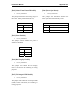
LED 10 (12V DC)
LED is lit steady Green when 12 VDC
power is present.
LED 11 (6V DC)
LED is lit steady Green when 6 VDC is
present.
LED 12 (28V DC)
LED is lit steady Green when 28 VDC is
present.
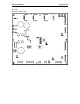
LED 13 (
Bar Display)
This LED’s indication depends on the
position of switch S3.
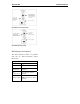
With switch S3 in the left position, this LED
displays the received signal (with a steady
Green bar) and Tag detection threshold
(with a flashing Green bar).
With switch S3 in the right position, this
LED displays the relative Tx power (with a
steady Green bar) and supervisor threshold
(with a flashing Green bar).
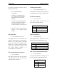
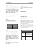
Table B.16
S3 Position LED13 displays:
Left
(Figure B.2)
Received signal
(steady Green bar)
Tag detection threshold
(flashing Green bar)
Right
(Figure B.3)
Tx Power
(steady Green bar)
Supervisor threshold
(flashing Green bar)