
User's Guide

Revised: 11/24/2020 6650-20-0014, Rev. A
Approval: Page 6 of 13
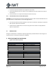
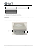
Figure 2 - Bottom View of ILB
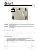
The following is an explanation of the IMN inputs and outputs as shown in Figure 1:
PoE INPUT: The ILB is powered by PoE. The power input to the ILB is an RJ45 connector on the back
side of the enclosure.
Status LED: The ILB contains a single red/green LED that indicates the status of the device (power
on, identification).
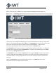
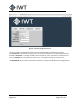
5. CONFIGURING THE ILB
Prior to installation, the ILB may be configured using a laptop/tablet/phone and the ILB’s internal
Configuration Webpage. The default configuration settings are shown in Figures 5 through 8 below.
The device must be powered ON to be configured.
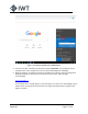
With the device powered on:
1. Click on the wireless network icon in the bottom corner of the laptop screen (or search for
wireless devices on tablet/phone) to view available Wi-Fi networks.
2. Search for the ILB device to be configured. The ILB will appear in the list of wireless networks as
ILBeacon-XXXX where ‘XXXX’ is the four-digit node ID listed on the label of the device. Each ILB
device has a unique ID.
PoE
Input