
Installation Instructions


CONFIDENTIAL
Page 3 of 4
DOC-850, SOP-01-1: Quality Document Template, Ver. 3
Once printed, this document becomes UNCONTROLLED. Please verify latest revision before each use.
DOC-9, SOP-01-1: Quality Document Template, Ver. 3
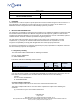
Figure 2. Location of pins 1 and 2
5. PROGRAMMING
The Purepath Wireless Configurator software is used to generate and load the wireless module
configuration files used in the Innovere system. For regulatory testing, the module can be loaded with
various regulatory test images using the Purepath Wireless Commander software. The wireless module is
programmed by using a Purepath Wireless Audio EB evaluation board and a CC debugger.
6. SOFTWARE CONTROL
The CC8530 on the Innovere Wireless Module is configured in host control mode. In this mode, the
device needs to be controlled by a host microcontroller using an SPI interface. The CC85xx Family User
Guide describes the commands that are used to control the wireless module, as well as the method of
sending the command packets over the SPI interface.
7. PAIRING PROCEDURE
The pairing feature of the wireless modules allows the components of the Innovere system to be modular,
meaning that any individual component of the wireless pathway can be swapped out in the field without
having to reprogram or reconfigure it.
Each wireless module is identified using two different names. The device ID is a 32-bit value that is
hardcoded and unique for every CC8530 device. The product ID is a 32-bit value that is written into the
flash memory of the CC8530 chip and is different for each individual component in the wireless pathway
of the Innovere system. Every slave component of the wireless audio pathway has been configured to
only recognize masters with a specific product ID depending on the component.
When the slave module is started up in pairing mode, it will scan for a network broadcast by a master
module with the correct product ID. Upon finding a suitable master, the slave will attempt to connect to it,
and upon a successful connection will store its unique device ID in its internal memory.
When the slave module is started up in its regular connection mode, it will scan for and connect to the
master whose unique device ID is stored in its internal memory.
8. DATA SIDE CHANNEL
The data side channel (DSC) is a stream of user-specified data that is sent alongside the audio data
stream in the wireless pathway. This data channel is bidirectional and can used to send packets of
generic data bytes. In the Innovere system, DSC packets are currently only sent upstream (from the slave
to the master) and is used to communicate connection status and battery level. When connected to a
master, the slave module will periodically feed data upstream to the master. Likewise, the master is set to
periodically poll its DSC buffer for data received from the slave.