
User Manual


4
ELECTRICAL CONNECTIONS
C520/C520X / R520/R520X
09/2010 • 86B5200001 www.inor.com 17
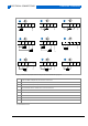
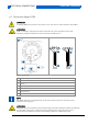
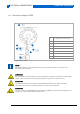
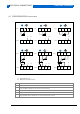
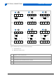
4.4 Connection diagram C520X
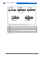
1
Zener barrier or voltage supply
10…30 VDC (intrinsically safe)
2
Input
3
Output
4
See “cable length”
5
Modem
6
Modem / Ex-approved
7
Safe area
8
Potentially explosive area
Figure 8: C520X connection
NOTE!
The HART modem is connected parallel to the output load or parallel to the output of the
transmitter (see Figure 8).
ATTENTION!
The transmitter may be operated in areas with potentially explosive atmospheres if the voltage
supply is ensured by means of an appropriate power supply unit or a Zener barrier!
ATTENTION!
In potentially explosive areas only Ex approved HART modems may be used. The safety
instructions for operation in potentially explosive areas must be observed.
ATTENTION!
In order to ensure reliable HART communication with C520X, the maximum cable length of the
output circuit must be observed (see Chapter 4.8).
R≥250 Ω
USB
1
2
3
4
5
6
7
8