
User Manual

USER INSTRUCTIONS English
Isolation Transmitter
www.inor.com
Read these instructions before
using the product and
retain for future information.
1. Before Startup 1. Before Startup
When operating the isolating transmitter, certain parts
of the module can carry dangerous voltage! Ignoring the
warnings can lead to serious injury and/or cause
damage!
When operating the isolating transmitter, certain parts
of the module can carry dangerous voltage! Ignoring the
warnings can lead to serious injury and/or cause
damage!
The isolation transmitter should only be installed
and put into operation by qualified staff. The staff
must have studied the warnings in these operating
instructions thoroughly.
The isolation transmitter should only be installed
and put into operation by qualified staff. The staff
must have studied the warnings in these operating
instructions thoroughly.
The transmitter may not be put into operation if the
housing is open.
The transmitter may not be put into operation if the
housing is open.
In applications with high operating voltages
sufficient distance and isolation as well as shock
protection must be ensured.
In applications with high operating voltages
sufficient distance and isolation as well as shock
protection must be ensured.
Safe and trouble-free operation of this device can
only be guaranteed if transport, storage and
installation are carried out correctly and operation
an maintenance are carried out with care.
Safe and trouble-free operation of this device can
only be guaranteed if transport, storage and
installation are carried out correctly and operation
an maintenance are carried out with care.
Appropriate safety measures against electrostatic
discharge (ESD) should be taken during range selection
and assembly on the transmitter.
Appropriate safety measures against electrostatic
discharge (ESD) should be taken during range selection
and assembly on the transmitter.
2. Short description 2. Short description
The 3-way isolation transmitter is used for electrical isolation and
conversion of 0 - 20 mA, 4 - 20 mA and 0 - 10 V signals. For
applications where normally only one signal combination is used,
IsoPAQ-41P offers a cost-effective alternative. The signal
combination is selected by the Part No.
The 3-way isolation transmitter is used for electrical isolation and
conversion of 0 - 20 mA, 4 - 20 mA and 0 - 10 V signals. For
applications where normally only one signal combination is used,
IsoPAQ-41P offers a cost-effective alternative. The signal
combination is selected by the Part No.
The 3-way isolation guarantees reliable decoupling of the sensor
circuit from the processing circuit and prevents linked measurement
circuits from influencing each other. The Protective Separation with
high isolation level provides protection for personnel and
downstream devices against impermissibly high voltage.
3. Functioning 3. Functioning
The input signal is modulated and then electrically decoupled using
a transformer. The isolated signal is then made available at the
output, demodulated, filtered and amplified.
The input signal is modulated and then electrically decoupled using
a transformer. The isolated signal is then made available at the
output, demodulated, filtered and amplified.
4 Equipment 4 Equipment
A screwdriver with a width of 2.5 mm is required to connect the
wires to the screw clamp terminals.
A screwdriver with a width of 2.5 mm is required to connect the
wires to the screw clamp terminals.
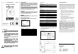
5. Mounting, electrical connection 5. Mounting, electrical connection
The isolation transmitter is mounted on standard 35 mm DIN rail. The isolation transmitter is mounted on standard 35 mm DIN rail.
Terminal assignments Terminal assignments
1 Input + Current
2 Input - Current
3 Input + Voltage
4 Input - Voltage
5 Output +
6 Output -
7 Power supply
≅
8 Power supply
≅
6. Order information
Product Input / Output Part No.
IsoPAQ-41P 0 - 20 mA / 0 - 20 mA 70ISP41012
4 - 20 mA / 0 - 20 mA 70ISP41032
0 - 10 V / 0 - 20 mA 70ISP41052
0 - 20 mA / 4 - 20 mA 70ISP41014
4 - 20 mA / 4 - 20 mA 70ISP41012
0 - 10 V / 4 - 20 mA 70ISP41054
0 - 20 mA / 0 - 10 V 70ISP41016
4 - 20 mA / 0 - 10 V 70ISP41036
0 - 10 V / 0 - 10 V 70ISP41056
7. Technical Data
Input
Input signal
(factory set as ordered)
0 - 20 mA 4 - 20 mA 0 - 10 V
Input resistance
Current input
Voltage input
22 Ω
1 MΩ
Input capacitance
Approx. 1 nF
Overload
Current input
Voltage input
≤ 200 mA
Voltage limitation via 30 V Z-Diode,
max. continuous current 30 mA
Output
Output signal
(factory set as ordered)
0 - 20 mA 4 - 20 mA 0 - 10 V
Load
Current output
Voltage output
≤ 600 Ω
≤ 1 kΩ
Linear transmission range - 2 ... + 110 %
Ripple < 10 mV
rms
General data
Transmission error
± 0,1 % of end value
Temperature coefficient
1)
± 0,005 %/K of end value
Cut-off frequency (-3 dB) > 1 kHz
Test voltage 4 kV, 50 Hz
Input against output against power supply
Working voltage
2)
(Basic insulation)
600 V AC/DC for overvoltage category II and
contamination class 2 acc. to EN 61010 part 1
Protection against
dangerous body currents
2)
Protective Separation by reinforced insulation acc.
to EN 61010 part 1 up to 300 V AC/DC for
overvoltage category II and contamination class 2
between input and output and power supply.
Ambient temperature
Operation
Transport
and storage
- 20 °C to + 70 °C (-4 to 158 °F)
- 35 °C to + 85 °C (-31 to 185 °F)
Power supply 20 to 253 V AC/DC AC 48 ... 62 Hz, approx. 2 VA
DC approx. 1,0 W
EMC
3)
EN 61326 -1
Construction 12,5 mm (0.5’’) housing, protection type: IP 20
Connection
≤ 2.5 mm
2
, AWG 14
Weight Approx. 100 g
1) Average TC in specified operating temperature range
2) As far as relevant the standards and rules mentioned above are considered
by development and production of our devices. In addition relevant assembly
rules are to be considered by installation of our devices in other equipments.
For applications with high working voltages, take measures to prevent
accidental contact and make sure that there is sufficient distance or insulation
between adjacent situated devices.
3) Minor deviations possible during interference
8. Block diagram
9. Dimensions
LIMITED WARRANTY
INOR Process AB, or any other affiliated company within the
Inor Group (hereinafter jointly referred to as ”Inor”), hereby
warrants that the Product will be free from defects in materials
or workmanship for a period of five (5) years from the date of
delivery (”Limited Warranty”). This Limited Warranty is limited
to repair or replacement at Inor’s option and is effective only for
the first end-user of the Product. Upon receipt of a warranty
claim, Inor shall respond within a reasonable time period as to
its decision concerning:
1. Whether Inor acknowledges its responsibility for any
asserted defect in materials or workmanship; and, if so,
2. the appropriate cause of action to be taken (i.e. whether
a defective product should be replaced or repaired by
Inor).
This Limited Warranty applies only if the Product:
1. is installed according to the instructions furnished by
Inor;
2. is connected to a proper power supply;
3. is not misused or abused; and
4. there is no evidence of tampering, mishandling, neglect,
accidental damage, modification or repair without the
approval of Inor or damage done to the Product by
anyone other than Inor.
This Limited Warranty is provided by Inor and contains the only
express warranty provided.
INOR SPECIFICALLY DISCLAIMS ANY EXPRESS WARRANTY NOT
PROVIDED HEREIN AND ANY IMPLIED WARRANTY, GUARANTEE OR
REPRESENTATION AS TO SUITABILITY FOR ANY PARTICULAR
PURPOSE, PERFORMANCE, QUALITY AND ABSENCE OF ANY
HIDDEN DEFECTS, AND ANY REMEDY FOR BREACH OF CONTRACT,
WHICH BUT FOR THIS PROVISION, MIGHT ARISE BY IMPLICATION,
OPERATION OF LAW, CUSTOM OF TRADE OR COURSE OF DEALING,
INCLUDING IMPLIED WARRANTIES OF MERCHANTABILITY AND
FITNESS FOR A PARTICULAR PURPOSE. EXCEPT AS PROVIDED
HEREIN, INOR FURTHER DISCLAIMS ANY RESPONSIBILITY FOR
LOSSES, EXPENSES, INCONVENIENCES, SPECIAL, DIRECT,
SECONDARY OR CONSEQUENTIAL DAMAGES ARISING FROM
OWNERSHIP OR USE OF THE PRODUCT.
Products that are covered by the Limited Warranty will either
be repaired or replaced at the option of Inor. Customer pays
freight to Inor, and Inor will pay the return freight by post or
other “normal” way of transport. If any other type of return
freight is requested, customer pays the whole return cost.
INOR Process AB
PO Box 9125
200 39 MALMÖ
SWEDEN
Phone: +46 40 31 25 60
Fax: +46 40 31 25 70
E-mail: support@inor.se
Internet: www.inor.com
86BIS00027 2005-05