BT125, BT200, SL150, SX150, LHF97125, SX150-BHF, S97125, USO56 AND SL125OC PNEUMATIC BRAD NAILERS & STAPLERS ENGRAPADORAS NEUMÁTICAS CLOUEURS ET AGRAFEURS PNEUMATIQUES OPERATION and MAINTENANCE MANUAL MANUAL DE OPERACIÓN Y DE MANTENIMIENTO MANUEL D’INSTRUCTIONS ET D’ENTRETIEN BEFORE OPERATING THIS TOOL, ALL OPERATORS SHOULD STUDY THIS MANUAL TO UNDERSTAND AND FOLLOW THE SAFETY WARNINGS AND INSTRUCTIONS. KEEP THESE INSTRUCTIONS WITH THE TOOL FOR FUTURE REFERENCE.
INTRODUCTION The Bostitch BT125 & BT200, SL150, SX150, SX150-BHF, LHF97125, S97125, USO56 and SL125OC are precision-built tools, designed for high speed, high volume stapling. These tools will deliver efficient, dependable service when used correctly and with care. As with any fine power tool, for best performance the manufacturer’s instructions must be followed. Please study this manual before operating the tool and understand the safety warnings and cautions.
SAFETY INSTRUCTIONS EYE PROTECTION which conforms to ANSI specifications and provides protection against flying particles both from the FRONT and SIDE should ALWAYS be worn by the operator and others in the work area when connecting to air supply, loading, operating or servicing this tool. Eye protection is required to guard against flying fasteners and debris, which could cause severe eye injury. The employer and/or user must ensure that proper eye protection is worn.
TOOL SPECIFICATIONS All screws and nuts are metric. MODEL LENGTH HEIGHT BT125 BT200 SX150 SL150 SX150-BHF LHF97125 S97125 USO56 SL125OC 10-1/8” 10-1/8” 10-1/8” 10-1/8” 10-1/8” 10-1/8” 10-1/8” 10-1/8” 10-1/8” 8-1/4” 9-5/8” 9-5/8” 9-5/8” 9-5/8” 8-1/4” 8-1/4” 7-5/8” 8-1/2” (257.1mm) (257.1mm) (257.1mm) (257.1mm) (257.1mm) (257.1mm) (257.1mm) (257.1mm) (257.1mm) (209,6 (244.0 (244.0 (244.0 (244.0 (209.6 (209.6 (178.0 (204.
OPERATION There are three available systems on BOSTITCH pneumatic tools. They are: 1. CONTACT TRIP OPERATION 2. SEQUENTIAL TRIP OPERATION 3. TRIGGER OPERATION CONTACT TRIP: The common operating procedure on “Contact Trip” tools is for the operator to contact the work to actuate the trip mechanism while keeping the trigger pulled, thus driving a fastener each time the work is contacted. This will allow rapid fastener placement on many jobs. All pneumatic tools are subject to recoil when driving fasteners.
AIR SUPPLY AND CONNECTIONS Do not use oxygen, combustible gases, or bottled gases as a power source for this tool as tool may explode, possibly causing injury. FITTINGS: Install a male plug on the tool which is free flowing and which will release air pressure from the tool when disconnected from the supply source. HOSES: Air hoses should have a minimum of 150 p.s.i. (10.6 kg/cm2) working pressure rating or 150 percent of the maximum pressure that could be produced in the air system.
LOADING THE BT125, BT200, SL150, SX150, LHF97125, USO56, SL125OC & S97125 EYE PROTECTION which conforms to ANSI specifications and provides protection against flying particles both from the FRONT and SIDE should ALWAYS be worn by the operator and others in the work area when connecting to air supply, loading, operating or servicing this tool. Eye protection is required to guard against flying fasteners and debris, which could cause severe eye injury.
DIAL-A-DEPTH™ FASTENER CONTROL ADJUSTMENT The DIAL-A-DEPTH™ Fastener control adjustment feature provides close control of the fastener drive depth: from flush with the work surface to shallow or deep countersink. First set the air pressure for consistent drive in the specific work as described on page 4, then use the DIAL-A-DEPTH™ fastener control adjustment to give the desired depth of drive. DEPTH ADJUSTMENT NUT Note: Any tools that do not come in a kit will have a non-adjustable depth of drive.
TOOL OPERATION EYE PROTECTION which conforms to ANSI specifications and provides protection against flying particles both from the FRONT and SIDE should ALWAYS be worn by the operator and others in the work area when connecting to air supply, loading, operating or servicing this tool. Eye protection is required to guard against flying fasteners and debris, which could cause severe eye injury. The employer and/or user must ensure that proper eye protection is worn.
TOOL OPERATION CHECK: CAUTION: Remove all fasteners from tool before performing tool operation check. 1. TRIGGER OPERATED TOOL: A. With finger off the trigger, hold the tool with a firm grip on the handle. B. Place the nose of the tool against the work surface. C. Pull the trigger to drive. Release the trigger and cycle is complete. CAUTION: THE TOOL WILL CYCLE EACH TIME THE TRIGGER IS PULLED! 2. CONTACT TRIP OPERATION: A. With finger off the trigger, press the contact trip against the work surface.
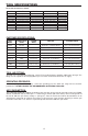
TROUBLE SHOOTING PROBLEM CAUSE Trigger valve housing leaks air O-ring cut or cracked . . . . . . . . . . . . . . . . . . . .Replace O-ring CORRECTION Trigger valve stem leaks air O-ring/seals cut or cracked . . . . . . . . . . . . . . . .Replace trigger valve assembly Frame/nose leaks air O-ring or Gasket is cut or cracked . . . . . . . . . .Replace O-ring or gasket Bumper cracked/worn . . . . . . . . . . . . . . . . . . . .Replace bumper Frame/cap leaks air Damaged gasket or seal . . . . . . . .
INTRODUCCIÓN Los modelos Bostitch BT125 y BT200, SL150, SX150, SX150-BHF, LHF97125, S97125, USO56, SL125OC, son herramientas construidas a precisión, diseñadas para funcionar a alta velocidad y con alto volumen. Estas herramientas entregan un servicio eficiente y fiable cuando se usan correctamente y con cuidado. Al igual que con toda herramienta automática de calidad, deben seguirse las instrucciones del fabricante para obtener el óptimo rendimiento.
INSTRUCCIONES DE SEGURIDAD Cuando el equipo está conectado al suministro de aire, tanto el operador como todas las personas que se encuentren en el área de trabajo, SIEMPRE deben usar PROTECCIÓN OCULAR que cumpla las especificaciones ANSI para resguardo contra partículas volantes arrojadas desde el FRENTE o los LATERALES. Dicha protección ocular se requiere para proteger contra residuos y remaches volantes, que podrían causar graves lesiones en los ojos.
ESPECIFICACIONES DE LA HERRAMIENTA Todos los tornillos y tuercas son métricos MODELO LONGITUD ALTURA BT125 BT200 SX150 SL150 SX150-BHF LHF97125 S97125 USO56 SL125OC 257,1mm 257,1mm 257,1mm 257,1mm 257,1mm 257,1mm 257,1mm 257,1mm 257,1mm 209,6 244,0 244,0 244,0 244,0 209,6 209,6 178,0 204,7 (10-1/8”) (10-1/8”) (10-1/8”) (10-1/8”) (10-1/8”) (10-1/8”) (10-1/8”) (10-1/8”) (10-1/8”) mm mm mm mm mm mm mm mm mm (8-1/4”) (9-5/8”) (9-5/8”) (9-5/8”) (9-5/8”) (8-1/4”) (8-1/4”) (7-5/8”) (8-1/2”) ANCHURA PESO
OPERACIÓN Se dispone de tres sistemas operativos para las herramientas neumáticas de BOSTITCH. Éstos son: 1. OPERACIÓN DE DISPARO POR CONTACTO 2. OPERACIÓN DE DISPARO SECUENCIAL 3. OPERACIÓN POR GATILLO DISPARO POR CONTACTO: El procedimiento de operación común para las herramientas de “Disparo por Contacto” es que el operador hace contacto con el objeto a ser clavado para activar el mecanismo de disparo, manteniendo halado el gatillo.
SUMINISTRO DE AIRE Y CONEXIONES No use oxígeno, gases combustibles o gases embotellados como una fuente de suministro para esta herramienta, ya que la herramienta puede estallar, posiblemente causando lesiones. CONEXIONES: Instale un enchufe macho en la herramienta que fluya libre y que descargue la presión de aire de la herramienta cuando sea desconectada de la fuente de suministro.
CARGA DE LOS MODELOS BT125, BT200, SL150, SX150, LHF97125, USO56, SL125OC & S97125 Cuando el equipo está conectado al suministro de aire, tanto el operador como todas las personas que se encuentren en el área de trabajo, SIEMPRE deben usar PROTECCIÓN OCULAR que cumpla las especificaciones ANSI para resguardo contra partículas volantes arrojadas desde el FRENTE o los LATERALES.
AJUSTE DE CONTROL DE ENGRAPADO DIAL-A-DEPTH™ La característica de control de engrapado DIAL-A-DEPTH™ aporta un control más exacto de la profundidad de impulso de las grapas: desde al ras con la superficie de trabajo hasta avellanado leve o profundo. Primero establezca la presión de aire para la aplicación uniforme según el trabajo específico como se describe en la página 14, luego use el ajuste de control de engrapado DIAL-A-DEPTH™ para dar la profundidad deseada a la aplicación.
OPERACIÓN DE LA HERRAMIENTA Cuando el equipo está conectado al suministro de aire, tanto el operador como todas las personas que se encuentren en el área de trabajo, SIEMPRE deben usar PROTECCIÓN OCULAR que cumpla las especificaciones ANSI para resguardo contra partículas volantes arrojadas desde el FRENTE o los LATERALES. Dicha protección ocular se requiere para proteger contra residuos y remaches volantes, que podrían causar graves lesiones en los ojos.
VERIFICACIÓN DE LA OPERACIÓN DE LA HERRAMIENTA: ¡PRECAUCIÓN: Quite todos los sujetadores de la herramienta antes de efectuar la verificaciÓn de la operaciÓn de la herramienta! 1. HERRAMIENTA OPERADA POR GATILLO: A. Con el dedo alejado del gatillo, sostenga la herramienta tomándola firmemente por la manija. B. Coloque la nariz de la herramienta contra la superficie del trabajo. C. Hale del gatillo para impulsar. Suelte el gatillo para completar el ciclo.
DIAGNÓSTICO DE FALLA PROBLEMA Fuga de aire en la envoltura de la válvula disparadora. Vástago de la válvula disparadora tiene fuga de aire. Fuga de aire en el armazón/nariz. Fuga de aire en el armazón/tapón. No desempeña su ciclo. CAUSA CORRECCIÓN Anillo en O cortado o rajado . . . . . . . . . . . . . . .Reemplazar el anillo en O. Anillos en O/sellos cortados o rajados. . . . . . . .Reemplazar anillo en O/sellos. Anillo en O/empaquetadura cortada o rajada . .
INTRODUCTION Les pistolets pneumatiques Bostitch BT125, BT200, SL150 et SX150, SX150-BHF, LHF97125, S97125, USO56 et SL125OC sont des outils de précision conçus pour fonctionner à haute vitesse et fournir un haut rendement. Ils offrent un service efficace et fiable lorsqu’ils sont utilisés correctement et avec soin. Comme pour tout outil puissant et sophistiqué, il faut suivre les instructions du fabricant pour obtenir de meilleures performances.
CONSIGNES DE SÉCURITÉ UNE PROTECTION DES YEUX, conforme aux normes ANSI et fournissant une protection contre les projectiles en provenance de l’AVANT et des CÔTÉS, doit toujours être portée par l’opérateur et les personnes présentes dans la zone de travail, lors du raccordement au réseau d’air, du chargement, du fonctionnement et de la maintenance de l’outil.
SPÉCIFICATIONS DE L’OUTIL Toutes les dimensions de vis et d’écrous sont exprimées en métrique MODÈLE LONGUEUR HAUTEUR LARGEUR HAUTEUR BT125 BT200 SX150 SL150 SX150-BHF LHF97125 S97125 USO56 SL125OC 257,1mm 257,1mm 257,1mm 257,1mm 257,1mm 257,1mm 257,1mm 257,1mm 257,1mm 209,6 mm (8-1/4po) 244,0 mm (9-5/8po) 244,0 mm (9-5/8po) 244,0 mm (9-5/8po) 244,.
OPÉRATION Il existe trois modes d’utilisation pour les outils pneumatiques BOSTITCH : 1. DÉCLENCHEMENT À LA VOLÉE 2. DÉCLENCHEMENT AU COUP-PAR-COUP 3.
ALIMENTATION EN AIR COMPRIMÉ ET RACCORDEMENT L’oxygène, les gaz combustibles ou les bouteilles de gaz ne doivent en aucun cas être employés comme source d’énergie, car ils peuvent exploser et provoquer des blessures. RACCORDEMENTS : Installer le raccord mâle sur l’appareil. Lors du désaccouplement de la source d’énergie, le raccord mâle doit permettre rapidement la mise à l’atmosphère de toute pression résiduelle.
CHARGEMENT DE BT125, BT200, SL150, SX150, LHF97125, USO56, SL125OC ET S97125 UNE PROTECTION DES YEUX, conforme aux normes ANSI et fournissant une protection contre les projectiles en provenance de l’AVANT et des CÔTÉS, doit toujours être portée par l’opérateur et les personnes présentes dans la zone de travail, lors du raccordement au réseau d’air, du chargement, du fonctionnement et de la maintenance de l’outil.
COMMANDE DE RÉGLAGE DES DISPOSITIFS DE FIXATION DIAL-A-DEPTH™ La commande de réglage DIAL-A-DEPTH™ permet de contrôler précisément la profondeur de pénétration des dispositifs de fixation : encastrement faible, peu profond ou profond. Réglez tout d’abord la pression d’air pour assurer une pénétration régulière dans un ouvrage donné, comme décrit à la page 24, puis utilisez la commande de réglage des dispositifs de fixation DIAL-A-DEPTH™ afin de régler la profondeur de pénétration souhaitée.
FONCTIONNEMENT DE L’APPAREIL UNE PROTECTION DES YEUX, conforme aux normes ANSI et fournissant une protection contre les projectiles en provenance de l’AVANT et des CÔTÉS, doit toujours être portée par l’opérateur et les personnes présentes dans la zone de travail, lors du raccordement au réseau d’air, du chargement, du fonctionnement et de la maintenance de l’outil.
VÉRIFICATION DU SYSTÈME DE DÉCLENCHEMENT : ATTENTION : retirer toutes les attaches de fixation de l’outil avant de procéder à une vérification du fonctionnement de celui-ci. 1. DÉCLENCHEMENT PAR LA DÉTENTE : A. Détente libre, maintenir fermement l’appareil par la poignée. B. Placer le nez de l’appareil sur la surface de travail. C. Appuyer sur la détente pour enfoncer un élément d’assemblage. Relâcher l’organe de service (détente) après chaque opération.
PROBLÈMES DE FONCTIONNEMENT PROBLÈME CAUSE CORRECTION Fuite d’air au corps de valve de détente. . . . . . . Joints toriques coupés ou usés. . . . . . . . . . . . . . . Fuite d’air à la tige de valve de détente. . . . . . . Joints toriques ou garnitures coupés ou usés. . . . . Fuite d’air entre le corps et le nez. . . . . . . . . . . . Vis du nez desserrées. . . . . . . . . . . . . . . . . . . . . . Joints toriques ou garniture coupés ou usés. . . . . . Amortisseur coupé ou usé. . . . . . . . . . . . . .