
User's Manual


Doc.: HD0389-00-Manuale_TL_GWCxxxx_r.0.1_EN.doc-00 17/04/2011 Page 6 of 49
1.2. GWC: description
GWC system has been designed to accomplish two main functions:
• Communication protocol converter/adapter (gateway)
• Programmable I/O device
The communication protocol converter/adapter function allows different field
buses – such as CanOpen, DeviceNet, ProfiBus, ModeBus, and in the future
Ethernet, to be handled/interfaced.
The programmable I/O device function allows user to write an automation
procedure that will be executed by the GWC device.
Such automation procedure can interface both digital and analog I/Os available
on the GWC device.
Both functions could coexist on the same device, allowing user a whole range of
possibilities to automate an industrial process.
GWC device is designed to guarantee enforceability of EN61800-3 and 60204-1
rules: to satisfy such rules user must guarantee connections characteristics
compliant with EMC immunity and emission, such as a ground connection, a
correct installation and a power supply filter.
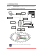
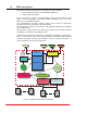
Figure 1: GWCxxxx functional block diagram
Profibus
Slave
Configuration
Parameters
Object Dictionary
DLL I/O
I/O
DLL Gateway
S1 Modbus
Slave
DeviceNET
Slave
S0 Modbus
Slave
DLL
Tripos / Codesys
Tripos / Codesys
User Application
DLL CANopen
Requests Queue
Handling
CAN # 1:
DLL CANopen Master #1
CANopen
Slave
Device
# 1
CANopen
Slave
Device
# 126
CAN # 2:
DLL CANopen Master #2
CANopen
Slave
Device
# 1
CANopen
Slave
Device
# 126
Boot
Program