
User's Manual


Doc.: HD0389-00-Manuale_TL_GWCxxxx_r.0.1_EN.doc-00 17/04/2011 Page 7 of 49
CanOpen#1
Interface
(1)
CanOpen#2 (5A)
or DeviceNet (5B)
Interface (1)
ModBus#1
RS232/485
Interface (1)
ModBus#2
RS232/485
Interface (1)
ProfiBus
Interface
(1)
Fast PNP
Digital Inputs
(8)
Source (PNP)
Digital Outputs
(8)
TRASPONDER#1
Interface
(1)
TRASPONDER#2
Interface
(1)
Controller
User Dip-Switches
7segm. Display
Ext. Flash
Memory
(up to 2Mbytes)
Ext. Fast SRAM
Memory
(up to 1Mbytes)
Ext. EEprom
Memory
(up to 32Kbytes)
Single DC Input Supply
Isolated DC to DC Converter
CN1
CN2
CN3
CN4
CN5
CN6
CN7
CN8 CN12 CN13
1 2 3
4
5
6
7
8
9
10
11 12
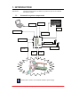
GW00 : Main Board
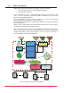
1.3. GWC hardware
Figure 2 shows the hardware block diagram of a GWC device.
This manual holds information about installation, start-up and service of a GWC
device. Please note that some function could be missing, depending on the GWC
device version.
Figure 2: GWCnnnn device hardware block diagram
i